

nILS
-
Posts
4,314 -
Joined
-
Last visited
-
Days Won
4
Content Type
Profiles
Forums
Blogs
Gallery
Everything posted by nILS
-
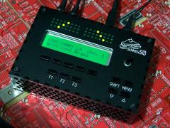
Beautiful! Love the casework, nice job! :thumbsup:
-
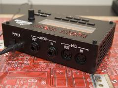
The outputs are at line level and not headphone outs. A headphone amp should solve that ;)
-
Oh btw, I totally need one.
-
v1 and v2 don't differ concerning the CS as much as you seem to think. As for the comparison - they don't compare well. Just look at the feature list of the mbSID v2 and compare it to the sidstation. Start with 8 SID chips vs. 1 ;)
-
"Do I want one" is a really bad question to ask, since you've got severe GAS. It should be "can I buy one w/o my wife getting mad at me" :flowers: I think you don't want one, but you wanna make one yourself. So much more fun :)
-
A 9V wallwart will do just fine. How will you use it? Plug it in the wall? The purpose of a power supply is to, erm, supply power. Try removing the power supply from your PC and see how well it runs ;)
-
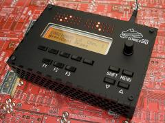
Very nice custom CS, me likey! Green FTW! :thumbsup:
-
The reason kaleaf thinks it's the wrong core is that there's few/no apps for the mios32 yet. So you'll either have to code your own or wait till it happens ;)
-
 Very nom! :console:
 -
I second this notion and officially order everyone too be ashamed of themselves. In the meantime: :frantics: Alles Gute zum Purzeltag, Thorsten!
-
I think the idea was to have an extended "Step B" CS - 40x2 LCD + 10 LCD buttons + menu encoder and menu buttons. The 5 extra encoders (for direct access to the "knobs" values) do not necessarily have to be in any way assigned or connected to the menu buttons. You might wanna look for "elSID", "mxSID" and seppoman's "der brat" for some inspiration as they include some different concepts.
-
Gerbils are cute, that's all :)
-
Here ya go. Not very advanced, but it gets the job done. lcd2bmp.zip
-
I made a little (windows) app for that a while back. I'll see if I can dig it up :)
-
I think your best bet is to write an eMail to Greg.
-
Reverse auction, yay! I got one you can have for $41,000 :yes: Oh and flexi: NAS is on the S|M forum, get your nicks straight ;)
-
*While* you push down the multimeter probe on a bad solder joint it may well make a connection, especially SMD pins ;) Glad you got it to work! :frantics:
-
That does in fact seem rather odd. Just follow the path of the two MIDI outs from the gm5 to the sockets and check that all the parts in the path are correct and the soldering is good (pay special attention to the gm5 pins, maybe those two aren't soldered rigtht): MIDI Out 1: GM5:14 -> R32 (220) -> IC3:13 IC3:12 -> IC3:11 IC3:10 -> MIDIOut1:5 MIDIOut1:4 -> R31 (220) -> +5V MIDI Out 4: GM5:17 -> R12 (220) -> IC6:13 IC6:12 -> IC6:11 IC6:10 -> MIDIOut4:5 MIDIOut4:4 -> R11 (220) -> +5V Check continuity between each connection and make sure the resistors are 220 Ohm.
-
Is it possible to control the MB-6582 without control surface?
nILS replied to whizz's topic in MIDIbox Tools & MIOS Studio
Yes. By either using this or if you're on Windows beta testing this: http://midibox.org/forums/index.php?app=core&module=attach§ion=attach&attach_id=6610 -
 That's soooooo pretty! :frantics:
 -
 /me orders 25 now
 -
I offered 5,50 :)
-
 nom nom nom!
 -
//Turn on adc ADCON0bits.ADON = 1; //wait for adc to do conversion while (AD1CON1bits.DONE == 0) { continue; }[/code] IIRC it's /DONE, which means that in your source it's the wrong way around and should be [code] ADCON0bits.ADON = 1; AD1CON1bits.DONE = 1; //wait for adc to do conversion while (AD1CON1bits.DONE) continue; Otherwise the app will wait until it's "not done" which will result in an endless loop.
-
That should work nicely :)