nILS
-
Posts
4,314 -
Joined
-
Last visited
-
Days Won
4
Content Type
Profiles
Forums
Blogs
Gallery
Everything posted by nILS
-
Glad it all works now :) And on a sidenote: Fuses are evil and PICs don't have fuses :yes:
-
I'd say if you're working on this with Wilba you're in good hands ;) Since Wilba knows all the possible errors/problems/causes how about you tell us what you and Wilba have already tested, before we start the entire troubleshooting progress again?
-
I assumed you checked all the voltages and they were good (and checked as per ucapps.de), is that the case? ;) If you're having a broken component in the output stage that might well cause the issue. And the transistor is pretty much the only part capable of breaking. You can try to get the audio out directly from pin 27 of the SID. Replacing the transistor is definitely worth a shot.
-
Testing a MIDIbox SID v2.0 + Analog MS-20 Filter Clone
nILS replied to resistor's topic in MIDIbox SID
julien: musikding.de has very similar ones in different sizes as well. -
I'll just wait here till then :)
-
Correct, there's not much current draw at the 12V rail. How did you upload the presets? A corrupt upload may well lead to what you are describing. The best way of uploading the patches would be using the sid v2 editor found on ucapps.de Also you might just try making a new (simple) patch (try different waveforms, make sure ADSR is 0-0-15-0, no modulation, no filters). About the switchmode supply: Unless you get a nice (= usually relatively pricey) one you'll have audible clicks and pops on the audio out due to noise from the psu. If you find a cheap _and_ quiet one, please let us know :)
-
1) You don't have to erase the PIC. Ever. All you do is upload the new application. 2) Did you use MIOS Studioto upload the app, and did you enable "smart mode"? 3) The voltages you are feeding the regulators are fairly high. Are your vregs getting hot? 4) Is there a ground connection between core and SID module? (There should be) 5) You are using 6581s, right? (6581s need 12V, 8580/6582s need 9V)
-
No you don't have to, but it's generally fairly helpful to have an LCD at least for debugging.
-
The options I put in the poll are all options that I am willing to give a shot. Red on black has been tried before for instance and erm, well it's not all that readable :) So in short - no, color combinations that are not in the poll are not an option.
-
If you use a 7812/7912 pair you shouldn't have issues with the different loads. Your 7812 will get pretty warm though. Also the whole bridging sth to ground in front of a bridge rectifier shouldn't be necessary.
-
I'll possibly cave to the masses - added a poll, please pick your favorite color combination :)
-
See, I told you - you are evil!
-
It has 8 data lines, which is a kind of a giveaway ;) It's parallel, all good. I took the liberty of deleting your double post and fixing the font-tags.
-
Nicely spotted, W! :thumbsup: Berlin-Dresden is ~200km. From where I live this thingie is ~7km :)
-
<broken record>offsite doco bad...</broken record>
-
This order will close February 1st, 2010 Get in on the fun while this is still open! :frantics:
-
Here.
-
It's "(non-)volatile" not versatile or versalite ;) I was wrong about the (non-)volatile thing, I thought it was sth else :) So it doesn't really matter as the midibox will reset the "pot" positions after a restart anyways. Also I missed the fact that all of the faders are 100k, awesome :) It's correct that the Core can only speak to one SPI bus, but that doesn't mean one slave. It's a bus, ie you can have multiple slaves on the bus. (see http://en.wikipedia.org/wiki/Serial_Peripheral_Interface) It does require writing some code to mod a midibox app to match your needs, but it's really not as bad as you seem to think, and there's lotsa people here who I'm sure would be willing to help you out ;)
-
Haha, awesome, I didn't know your pad-per-hole actually had the exact size you used in your layout otherwise I woulda made it fit :) Nice work!
-
With those digi pots using I2C/SPI you'd have to drive them directly from free pic pins, which shouldn't be the problem though. You'd want the non-volatile version. Also I dunno if they resistances you need are available, so you'd probably have to get bigger ones and lose some of the resolution. This is me guessing btw.
-
I'm mightily busy studying so I couldn't be fukt explaining the problem, and was hoping for someone like you or Wilba to find it and fix it, which has happened now :) Just quickly wanted to make sure the wrong/incomplete info wasn't gonna be used.
-
http://downforeveryoneorjustme.com/http://www.renoise.com/
-
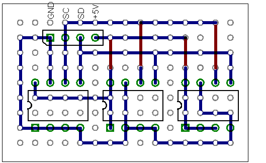
I generally try to work with pad-per-hole vero as if it were a "regular" pcb :) (just a quick layout to show the point) Solder the components first, then use resistor legs or thin wire and tack it on as "traces". Red is jumper wires on the component side. Doing it this way helped me not fuck up quite a few boards by now and they are physically pretty stable as opposed to using flying wire foo :)
-
Just a few thoughts on the side: - It's not going to be as simple as "replacing" the pots with a midibox controlled CV, as not all of the faders simply act as voltage dividers to supply a CV (see http://www.harpamps.com/schematics/). - A core8 will be more than enough performance-wise.
-