nILS
-
Posts
4,314 -
Joined
-
Last visited
-
Days Won
4
Content Type
Profiles
Forums
Blogs
Gallery
Everything posted by nILS
-
That's interesting - I build a proto one without the additional pullups and it worked... That _is_ the minimum config. You could get rid off the pullups if you by modding MIOS or just go with a way smaller chip (PIC16F88 comes to mind). Smaller chip would mean more programming though as MIOS won't run on it.
-
What are you missing? Some parts maybe? The pins you list are correct and should be sufficient, but it's really hard for us to guess what the problem is without further info. Do you get an upload request? Did you do the MIDI troubleshooting? Do you have pics?
-
The connection is 1:1 indeed. Make sure you have the cable on the right way round ;) If that's all good the srio_interconnection_test_v1b should pass. Try that.
-
Anyone designed a PCB for a midi controller / mixer channel strip?
nILS replied to intellijel's topic in Design Concepts
Oh and btw: You're wrong. There is a freeware version. The 30-day version is a test version of the full featured version. -
Correct, if you don't see anything happening, your DIN isn't working. Check the wiring (correct port? correct wires?)
-
This topic has been moved to Parts Questions. [iurl]http://www.midibox.org/forum/index.php?topic=13529.0[/iurl]
-
Find out if the DIN actually works. Use the ain64_din128_dout128_v2b from ucapps for that. Then we'll see ;) Make sure your core id is 0 and the CS is enabled in the software, too.
-
Anyone designed a PCB for a midi controller / mixer channel strip?
nILS replied to intellijel's topic in Design Concepts
Erm no. I just listed some options to consider. -
Neato, it looks a bit like the MFB synth. The blue panel kinda makes it look retroish to me very nice! :-)
-
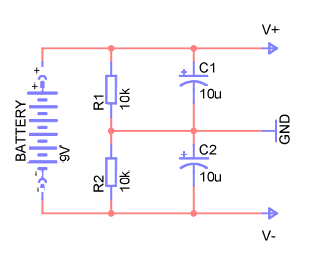
And then it could look as pretty as this: .-------.--------.---- + | | | | 10k 10uF + | | 9V >-------+---- GND - | | | 10k 10uF | | | `-------^--------^---- -[/code] And I totally don't understand why some people would prefer sth. like it's attached ;)
-
WIKI perhaps a prob, my workaround.
nILS replied to RoyalScam's topic in MIDIbox Documentation Project
Yep, at least google has the guts to call it beta. Unless other companies who'd call it "Vista" ;) -
This is often caused by a bad midi interface, did you check the blacklist on the wiki?
-
That doesn't look like a software bug ;) Can you take some pics of the wiring?
-
Bad ones shouldn't either, so shhh!
-
WIKI perhaps a prob, my workaround.
nILS replied to RoyalScam's topic in MIDIbox Documentation Project
The Adobe Reader 9 plugin in Chrome says: "The file is damaged and could not be repaired." When downloaded it does worlk though. Odd ;) -
The interconnection test will tell you if the relevant parts of the core/pic still work. It will however not tell you anything about the opl/yac/opamps. Although opamps are pretty forgiving the seem to dislike reversed polarity ;) I'd replace the opamps first, if that doesn't help you possibly fried the yac/opl.
-
K-rAd MB6401 is complete! check out the photo tutorial. It Works!!!!
nILS replied to K-rAd's topic in MIDIbox of the Week
The huge amout of pics and the doco you wanna write for the WIKI ;) -
K-rAd MB6401 is complete! check out the photo tutorial. It Works!!!!
nILS replied to K-rAd's topic in MIDIbox of the Week
Whoa, pretty box, nice doco! Congrats man! -
Ahahaha. Comedy gold.
-
I'd guess you'd wanna do that in MCLOCK_Tick(). I don't have the time to look over the code in depth, but you are aware that the note on event won't take a lot of time, right? It's not a matter of milliseconds but should be well in µs range, so I really doubt you'll need any compensation for that case ;)
-
This topic has been moved to Fleamarket. [iurl]http://www.midibox.org/forum/index.php?topic=13509.0[/iurl]
-
MIDIBox ist eine Bedrohung? Seit wann denn das? ;)
-
Working testtone app is a nice indicator - you're getting there. Now take one step at a time. Do you _know_ you midi keyboard or whatever you use is actually correctly sending out MIDI Notes on Channel 1? You could check that by running it into your PC and using MIOS Studio's input monitor to check the messages received. If that doesn't solve it, recheck the wiring once more. Take a close look at the schematics on ucapps.de and make sure you don't miss any of the subtle, small, tiny, semi-hidden wires ;)
-
As long as the voltage on the SIDs is not ~12V you can't really expect anything but static and noise. So first up you'll need a working PSU. The easiest way to achieve that would be to get a 11-15V wall wart and feed the SID modules with it. Remove all the ICs, plug in the new wallwart, measure the voltages - if they're all good, and you only get 12V where you're supposed to, put the ICs back in and prepare for some SID goodness ;) Giving up is not an option :D
-
Ooooooh! You better make sure your imaginary g/f never reads that ;)