Wilba
-
Posts
3,310 -
Joined
-
Last visited
-
Days Won
2
Content Type
Profiles
Forums
Blogs
Gallery
Everything posted by Wilba
-
You may have a faulty encoder. If the problem persists after cleaning up solder joints, the best solution is remove it cleanly (chop off pins above PCB, desolder pins one at a time) and replace it with a new one, which I can post to you.
-
Since MIDI works via a current loop, splitting the MIDI Out at the SOCKET probably won't work very well, both receivers would be sharing the current, and the optocouplers would get half the current or one would rob the other or some other weirdness... can't be sure exactly. It would be best to add a buffer (logic gate), fed from the point driving the MIDI Out... in a MIDIbox "Core" this would be the Tx pin of the PIC, between the 220 ohm resistor and the MIDI Out pin. Then the output of the buffer goes to 220 ohm resistor to the replicated MIDI Out socket. Remember that as the signal is high and low, it is sinking current from the other MIDI Out pin (connected to 5V via 220R), out the cable, through the receiving end, returning back in along the cable to the MIDI Out pin. So you replicate this bit too around the buffer. I have actually tried this with just a BC557 instead of a buffer (made a MIDI Thru by connecting BC557 to Rx pin of PIC). So unless you are planning to switch between the two, you do need some kind of buffer... or at least tap directly to the Tx pin or whatever is driving the MIDI and replicate the whole 5V->220R->socket->220R->Tx pin arrangement.
-
Perhaps the easiest solution is to add a switch between the AX's MIDI Out pins and the MIDI cable to the Widi-X8. As I see it, your use cases are mutually exclusive, you never want to use both MIDI Out socket AND Widi-X8 at the same time. So use a switch with a double pole. Connect the two switch "pole" pins to the AX's MIDI Out socket pins (easy to do, just solder to the PCB pads!), connect the two switch "throw" pins to the cable/MIDI plug going to the Widi-X8. Thus the switch will enable/disable the connection to the Widi-X8, the AX's MIDI Out socket will always be wired, but without a cable connected, it can't affect the Widi-8, since MIDI cables work by a current loop.
-
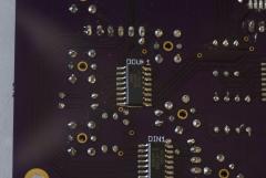 SMT FTW!
 -
Congratulations! Great photos!
-
 that's what she said
 -
I emailed the link to the v1.0 build guide but forgot to update the link in the wiki. Fixed now. Also, until the build guide is updated again, I recommend MIDIbox FM v1.4c which fixes issues with short notes for drum sounds. http://www.ucapps.de/mios/midibox_fm_v1_4c.zip
-
BUT RLY... **NSFW** http://images.cheezburger.com/completestore/2011/2/11/9082d762-bc49-4e97-89a3-b1f577304313.jpg **NFSW** YEEAAAAHHH!!!!!!!!!11111111oneleven
-
-
Heat transfer compound got stuck in customs because it's a chemical. Had to email them an MSDS.
-
They were bought on eBay. Search for "blue diffused 3mm" something like this: 50 Blue LED 3mm Diffused Blue Lens Bulb Free Resistor
-
It's preferred to solder the voltage regulators after attaching to the heatsinks/PCB via screws and then never moving it again. You could solder them without compound, but then you would need to bend the leads to apply it later. Not such a good idea, as bending it back might not result in as good a mating between the voltage regulator and the heatsink (i.e. not be as parallel). As much as I love PCBs with plated through holes and pads on both sides, I hate desoldering such pads, especially ground plane pads... so my attitude is perhaps different... I solder things with the intention to do it once and not touch it again. So the idea of even temporarily soldering voltage regulators and then desoldering later to do it properly with compound etc. just makes me cringe.
-
I've just tested v1.4c with FL Studio and tempo up to 999 and there are no dropped drum notes at all. Nicely done, TK! :D :cheer: I owe you zwei Biere. So now I can stop worrying that the sammichFM design is flawed.
-
See what you can get, PM me with details. They are listed as "yellow-green" same as my dead one. They are green enough to match with "green" LEDs since most "green" LEDs in tinted green diffused packages (like what I sell) are actually "yellow-green". You can get superbright/ultrabright "true green" in waterclear or white diffused packages, on eBay for example.
-
Sure, if you bring two of the 4x20 OLED displays :-) I need to replace the dead one in my prototype, plus one spare. Then I'll owe you some cash and/or beers!
-
Necro bump! I see your necro bump and raise you an obscenely large JPEG. I have plenty of those little PCBs that go above the LCD (at top and bottom). I probably have spares of the shorter switches you need to mount on them. It should be relatively easy to convert the production MB-6582 CS PCB to use these extra PCBs for the switches. The pads to connect them are on the PCB, to support such usage. WARNING! DO NOT STARE AT THE BLUE LEDS! YOU WILL GO BLIND!
-
Painted LEDs! I think you just started something big.
-
I think he means is heat transfer compound (of any kind) necessary, and I would answer no, it will work without it, just like a car will work without radiator coolant. (Yes, I'm being intentionally metaphorical). On a sidenote: Futurlec sucks. Even if you do get your order, it's mostly the absolute cheapest crap you could get. i.e. something might look like a Neutrik socket but be plated from stuff which will tarnish in a year and/or give you bad solder joints. If I knew years ago what I know now, I'd just pay the premium (of fixed $30 international postage) and get the good stuff from Mouser or Digikey, which have cheap prices anyway compared to local electronic stores.
-
Nice capture of the LCD... I can't seem to perfect that kind of shot.
-
As we say here, you gave me that on a platter (the joke setup). Just joking, not criticizing :poke:
-
You weren't on my loser list until after I heard this :tongue: Thank you, thank you very much. I'm here 'til Thursday. Try the veal.
-
OMFG that Optrex LCD looks filth. Great choice of paint colour. The LEDs rock... they look totally opaque and glossy when off, might be just the flash though.
-
I really should have tried harder... http://www.mgchemicals.com/products/860.html 4 gram singles at Mouser, part 590-860-4G, $0.90 each. Dammit, it has to be done. Buying 100 now. Expect them in sammich kits starting now! :thumbsup:
-
I can't understand why the non-conductivity of the heatsinking compound causes so much chatter. I should have just specified "white silicone goo". Actually, I should have just packed a squirt of the stuff in every kit, but I don't know how to pack it. Suggestions?
-
LOL At least you got to do some troubleshooting... I've not needed to on any board I've soldered myself in a long time... which is slightly boring. I don't even bother with voltage tests before plugging in ICs just hoping for a fried IC to locate and replace. *sigh* I suppose it's a good thing because troubleshooting aka. debugging aka. software development is my day job. The last time I had some head-scratching WTF moments was with the OPL3 module: Comment #7 is lulzworthy though. BTW that OPL3 module is totally redundant now. Free to a good home, inc. free shipping.