Wilba
-
Posts
3,310 -
Joined
-
Last visited
-
Days Won
2
Content Type
Profiles
Forums
Blogs
Gallery
Everything posted by Wilba
-
I test them all to make sure you get working SIDs. I'm confident that I might only get one or two SIDs from these 512 that dead, but why make one unlucky buyer find these? That would really annoy me (and has before ages ago when I bought four 8580 from some guy in Canada, I was assured all four were tested and all four were faulty!) Also, a lot of people buying SIDs are new to MB-SID and if their MB-SID doesn't make sound, I'd prefer they think it's their MB-SID and not the SID... this will help a lot in troubleshooting if you can assume the SID works.
-
Apologies to everyone, I've been really busy and haven't had time to test and pack all the SIDs. It's actually a very slow process, I have to reboot my MB-6582 for every SID and cut up the chip tube into smaller lengths etc. And the other day I got distracted with a bug (feature!) in the latest MB-SID V2 firmware which made the tested SID on the right channel sound like it had a different filter to my 6582A in the left channel... worked that one out (the SIDs are fine and identical). Anyway, just wanted to mention it... probably no one really cares if it takes one week or three weeks to get their SIDs but I still wish I had more free time to do this so people waited less.
-
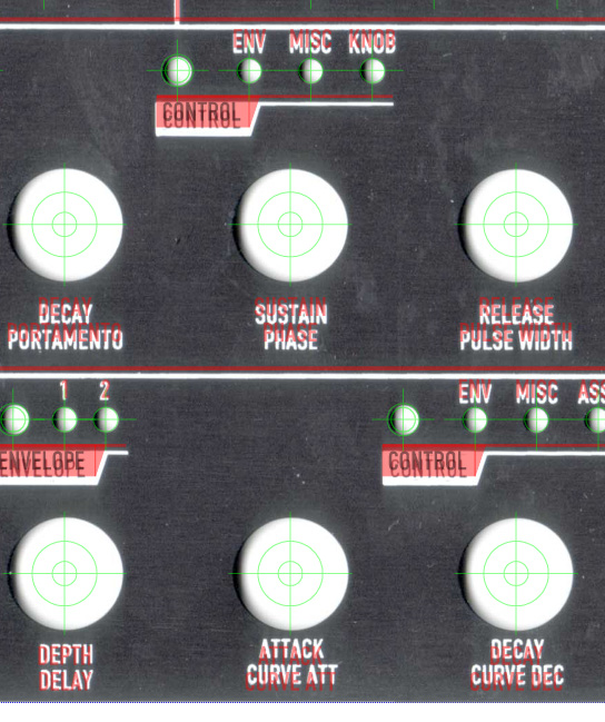
I have to say that the quality of the silk-screening leaves a lot to be desired, and I am not happy with the result at all. First, the paint is uneven, with the black showing through in places like the label backgrounds, bleeding into the black text making the black text thinner than the white text, and generally not what I expected from silk-screening. When I think of silk-screening, I expect the same kind of quality that you see on consumer products, essentially as fine-detailed as laser or inkjet printing. Please correct me if I'm wrong. Maybe the super-glossy paint makes it look worse, I don't know... but surely if you specify a solid white area, it should come out solid and not show spots of black. Secondly, the artwork is not what was specified by me. I discovered many alignment faults on individual labels and the lines are not where they should be. To demonstrate exactly how bad this is, I scanned the front panel I have and overlaid the original artwork (in red), along with the corner registration marks and hole placements. http://members.optusnet.com.au/~wilba6581/MB-6582_frontpanel_faulty.pdf If it was an alignment error for the entire artwork, you would see every line and label slightly out of alignment by the same amount. Likewise, if it was a scaling error for the entire artwork, you would see it incrementally change in alignment error across or down the panel. However, what you see in this PDF is how individual labels and lines are out of alignment in different ways, which can only happen if these things were explicitly moved by the printer either before they printed the screen or possibly after... I don' t know exactly why or how someone has done this, but I am extremely annoyed that it has been done without informing the customers (everyone participating in this bulk order). If there was some issue with the first printing they did, instead of moving things around to make them "fit", they should have consulted the customers (us) and requested a solution, new artwork, a different file format, not deciding to do a "fix" themselves and hoping the customers (us) would not notice or care about it being exactly right. Take a look at the filter mode labels (bottom left corner) and the LFO waveforms (right side). How can these be exactly aligned but everything else on the panel be out of alignment? Take a look at the labels for the bottom row of knobs. How can the words CUTOFF, RESONANCE, DEPTH, ATTACK, DECAY, SUSTAIN, RELEASE which are supposed to be vertically aligned (see red text) have different vertical alignments? This last alignment fault is the most annoying, because the labels are now too close to the knobs and shows up clearly when you put the knob on the hole, there is no longer a constant gap between the bottom of the knob and the label underneath it. I don't think I'm being picky or perfectionist about this... I spent hours fine-tuning the original artwork for my MB-6582 and then later with this silk-screen version, manually placing everything perfectly aligned so that labels are centered with LEDs and gaps between lines are consistent. I see these alignment faults as no less than explicit tampering of the original artwork by the printer and a complete disregard for the customer's expectation of quality and meeting the specifications they were given. Redone by who? The same people that have stuffed up this silk-screening two times? I would prefer to send it back to the fab and get a refund on the whole panel set. They had two chances to get it right. I don't trust them at all to meet the spec, not after the deliberate "tinkering" of the artwork that took place last time. This, more than anything else, is what I am really annoyed about, and I don't see why they should get another chance. I'm just being honest with everyone here... it would be a lot easier to just chuck my two panel sets in the bin and forget about this whole mess... but I felt that everyone else should know about how bad these panels are now and not later when you put the knobs on the fully constructed MB-6582. If it is not just me who feels the same way, then it would make sense to deal with it as a group.

-
I test them before I ship them. That's why it takes so long... there are currently 368 SIDs to be shipped. If they stay in the same, unopened, undamaged tubes that I ship them in, then they should work just as well as when I tested them. They've been sitting in these same tubes for 15 years so I think another few months won't make a difference. Plus I have never had a report of the SIDs I sell not working after they were delivered, so I wouldn't worry too much. If you really need to test them, buy a newer model C64 (check it has an 8580 in it) and a Prophet64 cartridge... that might be the quickest way if you REALLY need to test them. Or bypass the Prophet64 and just learn how to POKE the SID registers. I don't know C64 BASIC programming so you can find answers elsewhere. When it comes time to test them in an MB-SID, make sure you test all voltages first, check the PIC is receiving MIDI and the pins on the SID socket are being changed by the PIC and also test the audio buffer works (there are test apps for this). Then take out one SID and test it in one SID socket. If you don't hear sound, then work out what's wrong then, don't go plugging in every other SID you have, just in case you killed the first one for some reason.
-
Good questions! BC337: I don't know about varieties, I just used whatever I got from the store. Referring to the Core parts list: | Transistor BC337 | 1 | BC 337-16 | 0.06 | 0.06 [/code] http://www.ucapps.de/mbhp/mbhp_core_orderlist.txt I don't even know what the 16, 25, 30 means, is this voltage? BC547: This is your bog standard transistor. As far as I know, the A,B,C refer to different gains I think. Since these transistors are only ever used as current sinks, i.e. either sink nothing or 100mA, it doesn't really matter. The ones I used were marked BC547-C. You could probably stick any transistor there and it will work (except a darlington, the collector-emitter voltage is too high and the voltage of logic low seen on the DIN inputs would be close or above the logic low threshold).
-
I've had optocouplers fail on me, for no good reason. One day it works, the next it just didn't. It's not like I fried it with 14V or something. Optocouplers have a LED and phototransistor inside them... both of which could curl up and die due to a voltage spike I suppose, or an electrostatic discharge. That's my guess, I'm no expert. Stick in another optocoupler and I bet it will all work.
-
NAS, I did not intend my post to be a personal attack, just stating facts... your post did generate a very high "WTF?" response from me, but I'm not angry or annoyed. You certainly didn't waste my time like many others did. Sorry back at you.
-
Very interesting! Reminds me of the work of Peter Vogel: http://kinetica-museum.org/new_site/index.php?ptitle=artists%20Peter%20Vogel&%20mfile=artist.php?id=79 (just thought I'd add that for the people who might find it interesting).
-
DragonMaster, what are you concerned about? The tuning of the oscillators or making them all in phase or having gates synced?
-
I believe the line of black boxes is just the LCD's internal bootup test thing. Not all displays do that. One or two bars should be OK If you only get one SysEx message, that means MIOS is already installed (as it should be if the PIC comes from SmashTV). Only if you get repeated SysEx messages is MIOS not installed (just the bootloader). If you are not seeing "MIOS V1.9f" on the LCD and then the "READY." message then that's a Core->LCD problem.
-
You can't connect the same crystal to multiple PICs... and while I think it's possible to make multiple PICs sync to the same clock input, the PIC is using the special clock mode which quadruples the crystal frequency, i.e. the 10Mhz crystal is being used to create an internal 40Mhz clock, and I don't think you can get multiple PICs to sync to a 40Mhz clock input. Even if it was possible to get multiple PICs to sync at 40Mhz, there's still the issue of the master PIC running the control surface as well, so they will never be all exactly in sync anyway. I don't know what you mean by "timing differences the crystals have"... crystals are pretty accurate.
-
R6 is a pull-up resistor to keep the PIC's Rx pin (serial input) high when there's no signal coming from MIDI In, or the optocoupler (6N138) isn't connected. Since this board always connects the Rx pins of all the PICs, R6 on the slave PICs are redundant. It does not hurt to solder in those resistors - this is how people have connected multiple Cores together for years. SmashTV can help you with a Mouser part number perhaps... I got mine from a local electronics shop the first time, and the second time from SmashTV (as a base parts kit).
-
NAS, you showed interest in the PCBs before the first run, then completely ignored all future correspondence from me when asked to confirm an order and pay for it (both through email and PM). Why do you want a base kit and "control kit" when you don't have PCBs? Are you thinking the base kit contains the base PCB? It does not. What do you think is in a "control kit"? I don't even know, since it doesn't exist. Base kits should go to people who have already bought the PCBs and have them in their hands.
-
Didn't get in the first MB-6582 PCB bulk order? Then post here
Wilba replied to Slorrin's topic in Bulk Orders
-
Steve, I just had a look at your website www.abletonator.com Does your Abletonator also use MIDIbox hardware/firmware?
-
We all got lucky... Someone paid US$189.51 for an ugly box that sounds better than a SidStation. Flavio the profiteer probably made a loss... he probably covered his parts cost but for the time spent soldering and assembling that abomination he probably earned less than minimum wage. Maybe he's learned that you can't put junk on eBay for 3 days and expect a bidding war.
-
The SIDs are already well protected by an audio buffer. This mixer happens after the audio buffers. I thought about adding an amplifier but an eight channel amplifier off a single supply is a bit out of my league... and since most of the time people will want separate channels anyway, there wasn't much demand for it either. If you really want to treat the SID as one stereo device then plug it into a mic input with some more gain and be done with it (might as well use a "real" amp).
-
This is a passive mixed output of the four stereo channels, which you can connect to the small phono jack above the power switch. Totally optional. This was a late design idea I threw into the prototype, the resistors below each audio socket are used to connect the audio signals together when there is no plug in the switched audio socket, i.e. it will only mix those sockets without plugs. You need to connect it together with insulated wire under the board though.... I didn't want to mess up the ground plane with tracks. Basically join four unused pads together in two rows. I used 10K resistors there because that's what I've seen before in passive mixer designs, but the output is very attenuated, and I am guessing that you could drop these to 1K or less, as the outputs of the audio buffers after each SID can probably handle that. Someone with more audio electronics (and SID!) knowledge can probably answer that question.
-
Interesting circuit, but I don't like how the load isn't connected to the same ground. That makes life harder, or maybe I'm just paranoid, I wouldn't want an audio ground to be sitting on top of a MOSFET. Not that I'm starting a FUD campaign against the idea, I just don't know... This looks like an easier build... http://www.edn.com/index.asp?layout=article&articleid=CA6421439&spacedesc=designideas&industryid=44217 and appears like you can configure the press time required to toggle the power... I would then drive a MOSFET from the output to supply current to the rest of the circuit rather than sink it. I am intrigued by how simple this one is... I think I might try it out.
-
Oops... I just noticed the hole for the SID "R" LED overlaps a little with the corner mount of the PT-10 case. You can trim the plastic a bit, it should be fine.
-
SHIPPED: LCD 20x4 for MB6582, red-on-black: Europe order
Wilba replied to Kartoshka's topic in Bulk Orders
I wired up one of these displays last night... very nice... it still is an LCD, you can't overcome the viewing angle problems but it generally does look like kokiPsiho's photos... if you turn up the backlight to max, the black becomes a dark red (as you'd expect)... I'm thinking of perhaps putting some darkish tinted acrylic in front of it... reminds me of the Philips TV I grew up with, which had a red 7-segment LED display behind dark brown tinted plastic. -
Me Too!â„¢
-
Is that me or some other good friend of yours? *whack*
-
Just remember to kiss her and not the iron.
-
The right power switch (i.e. C64 power switch) has been found. I just need to buy 500 of them now. They will definitely end up in future "kits", probably not this batch of kits, but they are easy to send in a letter for $2 so I'm happy to distribute them to the MB-6582 builders. Please don't flood me with requests for them now, I am drowning in email already.