Wilba
-
Posts
3,310 -
Joined
-
Last visited
-
Days Won
2
Content Type
Profiles
Forums
Blogs
Gallery
Everything posted by Wilba
-
Crystalfontz CFAH2004A-xxx 20x4 LCD (for Wilbas MB-6582) for just US$ 9.99!!
Wilba replied to zid's topic in Parts Archive
Yes, don't worry, you're supposed to mount the LCD behind the PCB. After you've used the PCB as a guide for mounting the spacers to the panel, you can solder the switches on, but for the switches that overlap the LCD's PCB, you should solder the pads on the top side, and cut the pins on the bottom - so you can mount the LCD close to the PCB. I will explain this more in the construction guide soon. -
I added them on with superglue and then soldered the wires between them. The wire was perfect for this kind of work... i.e. soldering 5mm lengths of wire.
-
My 2 cents: get some Kynar™ wire, aka. wire wrap wire. Single 0·25 mm (30 a.w.g.) silver-plated copper solid conductor with Kynar™ insulation. This stuff is awesome. You can strip it to just a bare wire and make tracks on the perfboard, soldering it down at points, or make multiple insulated tracks on top of each other. The Kynar™will not melt like other plastic coated wires, and the single core makes it easy to solder, no need to tin the wire ends. It's useful in many other contexts too, like changing/fixing PCB tracks, and wiring SMD LEDs into this abomination:
-
UK/Europe Bulk order of "Waldorf" knobs for the MB-6582 (CLOSED)
Wilba replied to Goblinz's topic in Bulk Orders
The ALBS knobs got here in a small box with 100 inside (and some room to spare) for 10 Euro, and that was Germany to Australia. I wouldn't worry too much about postage costs. -
Tiramisu.... zabaglione..... *drool*
-
If you confirmed your SID order with me and I confirmed I could sell you that quantity, you should have received a PayPal invoice already and should have paid it already. Please contact me if you have not yet paid for your SIDs.
-
This is not a good idea... people will need to load the latest version anyway, as it's still a beta release at the moment, and I think everyone needs to demonstrate (learn!) some basic MIDIbox skills like uploading an app with MIOS Studio.
-
I count 3. Maybe. I've used mostly 100mil (0.1") spacing, because my original control surface design was to be done on veroboard/prototyping board. So for example, a switch with LEDs near it will be aligned so the switch can be centred on a hole and the LEDs aligned between two holes. However, this alignment is not constant over the entire control surface... i.e. not all switches would be aligned to a common 100mil grid. To demonstrate this, open the FPD file and change the grid to 0.1" and see how some switches are centered on a grid dot and others are not. So the only way to use veroboard with the panel layout as it is, would be making small sections, and then you probably won't have enough space to mount them to the panel as it's very compact. I don't know why you would want to do this anyway, the control surface PCB is cheap and the perfect compliment to the panel (that's the point!). Can you explain what you would want to do differently? If you're asking if you could do your own different panel design and use veroboard, then yes, you can do that, and construct it the same way (spacers glued to panel underside) but you would need to include more mounts as veroboard is a lot more flexible than a PCB with less holes and different material (fiberglass?). The encoder's aren't mounted directly to the panel (not the current panel design being produced) nor would it make sense to do so, the shafts would stick out far too much. You can mount them to veroboard too, the ones I use can mount nicely and the shaft can align to a hole in the board, the pins are approx. 200mil spacing and you can cut some notches to put the encoder's mounting tabs through the board and bend underneath (and even solder too). I'm not left handed. The filter section is on the left because that's the only way I could fit all the sections on the panel and still maintain 1.1" horizontal spacing between all the knobs in the lower four sections. (This is more important than you would think.) The menu encoder to the right of the display, which is also on the top right, is more important (for right handers) ;D
-
More Cowbell!!!!! http://www.youtube.com/watch?v=tt8bJdmUlSo ;D ;D ;D
-
UK/Europe Bulk order of "Waldorf" knobs for the MB-6582 (CLOSED)
Wilba replied to Goblinz's topic in Bulk Orders
Please deliver here -
You should consider building the minimum control surface for MB-SID V2 (this option has been formerly called "Step A Surface"): http://www.ucapps.de/midibox_sid_manual_fp.html It would be annoying if you upgrade to V2 and can't access the V2 features that are only accessible by pressing the SHIFT button. It requires only a DINx2, but leaves 5 inputs free, so you could even upgrade to a 2x40 LCD and add 5 extra select buttons (ideal solution for a minimum control surface!)
-
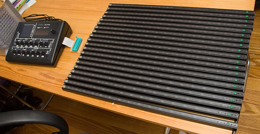
Some SID chips are dead, or have such low level output that they are as good as dead. All the SID chips I sell have gone through a quick test (see the ZIF socket in the picture) to make sure that the filter works and all three oscillators make noise and that it has approximately the same output level as my other SIDs. This means people don't have to send a dead SID back to me and get a replacement, I just find the dead SIDs now and save people this hassle (and as always, there's no guarantee I can get more SIDs).
-
AFAIK SmashTV is in the process of ordering some. Even I don't have these switches yet >:( and temporarily use a DPDT toggle switch with the same size.
-
Whole Lotta SID

-
The CS wiring diagrams show how the LEDs and switches are connected to the four ports on the bottom left of the base PCB, i.e. JD5, JD6, JD7, JD8 JD8 is the common "current sink" for all the LEDs and switches in the matrix, i.e the "columns" of the matrix. As shown in the CS wiring diagrams, JD6 is connected to horizontal "rows" of the 8x8 mod matrix LEDs, JD7 is connected to the "rows" of all the other CS LEDs, and JD5 is connected to the "rows" of the switch matrix. The firmware will manage sinking one pin of JD8 at a time, which will correspond to 8 "virtual" shift registers in the DIN and DOUT matrix (see where the shift registers are referred to as 16+1, 16+2 etc. in the setup_mb6582.asm file). So to do your own control surface, you can wire up all your switches and LEDs in any way you like, and then change the setup asm file to suit, EXCEPT for the 8x8 mod matrix LEDs, these really should be done exactly as shown. The JD1, JD2, JD3, JD4 ports connect directly to DIN shift registers and you can connect up to 16 encoders to these pins in any order, and configure it through the setup asm file as per the standard method of connecting encoders to a MIOS based application (these are just DIN modules, not a switch matrix). I don't see where you get the number 27. But you are right, I did not define the exact connections between the encoders on the CS PCB and the JD1-JD5 ports because it is not important exactly what order I used, people building their own CS can connect whatever they want to these ports. It was more important (for me and others) to explain how the common LED/switch matrix works, since this is what is different to the original "step C" control surface wiring. Until I update the wiring documents with this information, you can either a) trace it from the CS PCB wiring or b) look at the configuration in the setup_mb6582.asm tables eg. #if CS_MENU_USE_INCDEC_BUTTONS == 0 ENC_ENTRY 1, 6, MIOS_ENC_MODE_DETENTED2 ; menu encoder #endif ;; additional CS encoders ;; SR Pin Mode ENC_ENTRY 4, 4, MIOS_ENC_MODE_DETENTED2 ; Osc delay/transpose/assign #1 ENC_ENTRY 3, 0, MIOS_ENC_MODE_DETENTED2 ; Osc attack/finetune/assign #2 ENC_ENTRY 3, 4, MIOS_ENC_MODE_DETENTED2 ; Osc decay/portamento/assign #3 ENC_ENTRY 2, 0, MIOS_ENC_MODE_DETENTED2 ; Osc sustain/arpeggiator/assign #4 ENC_ENTRY 2, 4, MIOS_ENC_MODE_DETENTED2 ; Osc release/pulsewidth/assign #5 ENC_ENTRY 1, 0, MIOS_ENC_MODE_DETENTED2 ; LFO rate ENC_ENTRY 1, 4, MIOS_ENC_MODE_DETENTED2 ; LFO depth ENC_ENTRY 4, 2, MIOS_ENC_MODE_DETENTED2 ; Filter CutOff ENC_ENTRY 4, 6, MIOS_ENC_MODE_DETENTED2 ; Filter Resonance ENC_ENTRY 3, 2, MIOS_ENC_MODE_DETENTED2 ; Env depth/assign #1 ENC_ENTRY 3, 6, MIOS_ENC_MODE_DETENTED2 ; Env attack/assign #2 ENC_ENTRY 2, 2, MIOS_ENC_MODE_DETENTED2 ; Env decay/assign #3 ENC_ENTRY 2, 6, MIOS_ENC_MODE_DETENTED2 ; Env sustain/assign #4 ENC_ENTRY 1, 2, MIOS_ENC_MODE_DETENTED2 ; Env release/assign #5 [/code] This configuration was optimal for the traces on the CS PCB, you can change the S/R and pin to whatever suits your own CS design and minimal spaghetti wiring. I should also add that if people are designing their own CS, then I expect people to understand how the MB-SID "step C" control surface is wired (by default) and then know the base PCB has DINx5 and DOUTx3 modules on it and do what they like with it.
-
The PDFs for the DIN/DOUT matrices have been put on the wiki already.
-
No and most likely yes. Well, it's certainly a lot easier for you to just add another Core and use a dedicated application to manage your analog inputs and convert them to CC events. It is possible to modify the MBFM application to remove the control surface code and put in your own simple analog input code, but the only advantage would be to save on one Core module, and the disadvantages are plenty, like spending far too much time hacking a single Core solution and running into limits of CPU cycles and memory. Essentially if you have to ask this question, your ASM coding skills are obviously not adequate enough to know if it's too much for one Core to handle (and my ASM coding skills aren't adequate enough to give you a definite yes or no answer either). Adding another Core would also allow you to plug it into another MIDI controlled synth or the PC, so it's more flexible a solution. Check out ACSensorizer as a possible complete solution (if you only have 8 analog inputs, but weird and wonderful sensor types)
-
I have updated the wiki with the exact part number and datasheet for the encoders I use. http://www.midibox.org/dokuwiki/wilba_mb_6582_control_surface_parts_list Dimensions are L=20mm, plus the base is 6.5mm tall, making overall height above PCB of 26.5mm. I apologize to anyone who got confused by the link to the ALPS parts which have a different shaft length. If anyone got longer shaft encoders by accident (or because I told them the wrong dimensions), please accept my apologies. If they have plastic shafts, you can shorten them and extend the flat side of the shaft down to the bushing (threaded part).
-
If you are referring to: Mouser Part No: 318-ENC160F-24P Alpha Part No: RE160F-40E3-20A-24P I believe these are fine. You've obviously confirmed the other aspects (pin spacing, etc.). I think someone else linked to ALPS parts from the wiki, but the 25mm length is not the same as the ones I have, which are 20mm length, so overall height above PCB is 26mm. Therefore, the alpha encoders you see there are practically identical to mine. I've updated the parts list. I can confirm that with 26mm overall height, the Waldorf knobs push on the whole way with about 0.5mm gap between knob and panel.
-
I will take some videos of mine eventually... still working out how to attach the video camera to my head. ;D
-
UK/Europe Bulk order of "Waldorf" knobs for the MB-6582 (CLOSED)
Wilba replied to Goblinz's topic in Bulk Orders
I asked about the transparent red ones a few weeks ago and was told they're out of stock. -
Well... that's technically not true... I've left the holes for the encoder shafts at 14mm so you can still mount SMD LEDs to the encoder base and illuminate the knobs (like I did). While I don't think the end result is worth the effort, some people still want to learn from their own mistakes ;D FYI, where I blogged my own mistakes: http://www.midibox.org/forum/index.php?topic=8389.msg63060#msg63060
-
Because there is so much more you can do with MB-SID... no one even knew you could use feedback to get squelchy sounds until someone posted that link on the forum.
-
UK/Europe Bulk order of "Waldorf" knobs for the MB-6582 (CLOSED)
Wilba replied to Goblinz's topic in Bulk Orders
If by "blueish clear ones" you mean the ones on my MB-6582: then they no longer have these in stock (but I know who has the last of them ;) ). The website shows they do have transparent (and untinted) ones. -
PayPal invoices have been sent out now. I will be testing, packing and sending them next week.