

Altitude
-
Posts
1,184 -
Joined
-
Last visited
-
Days Won
30
Content Type
Profiles
Forums
Blogs
Gallery
Everything posted by Altitude
-
have not tried the OTG usb thing yet but will. I had no problem running the GM5 on my phone so it should work here
-
are you running the host on the computer? I didnt configure anything, all my physical midi ports were there as soon as I started the app. Running everything over wifi and OSC
-
I was looking for an excuse for a Nexus 7 so this is it. Of course I have the wrong magjack on mine which needs to be replaced first but as soon as that gets here, I'll give it a good workout. What is the compatibility with a V4L?
-

BLM-Scalar emulation JUCE app compiled for the Raspberry Pi
Altitude replied to borfo's topic in MIDIbox BLM
it would be cool is if could be connected to the SEQ via OSC -
will mbcv2 run on the lpc core? i can test that with my seqv4..
-
blm is the top of my list, i dont have my stmf4 core built yet but will shortly
-
So far so good. Been playing around with simpler projects and everything works as expected, the program will even reformat the projects for 16:9 Android tablets..
-
picked it up, I have a seqv4 here so I'll give it a go
-
Problem with CORE! Please help me! :(
Altitude replied to Los Zelos's topic in Testing/Troubleshooting
why are you using LTC? It's an obsolete module and not needed (at all). You flash the bootloader with a PIC programmer, then upload MIOS via MIDI, then upload the app via midi -
Problem with CORE! Please help me! :(
Altitude replied to Los Zelos's topic in Testing/Troubleshooting
You're not giving much info here. What programmer did you use to flash the bootloader and MIOS? -
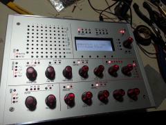
From the album: Altitude's pics
Transflective display! -
What voltage is being supplied to the SID? 8580 should be powered by 9V DC. They get warm but not that warm
-
you dont. That's why its called no clean
-
I use the LPC cores right now, I have a layout for CNCing the holes for those and right now. I am doing a second rev of the Aout board, the first one had a bunch of mistake since the schematic I used which I assumed was correct had a bunch of errors on it. The prototype worked fine with all the fixes though. If you are not familiar with soldering fine pitch surface mount parts, I recommend you learn on something else. The Max525 parts are SSOP size which is VERY fine and at $25 each, its not a part you want to practice on. This board was made with the smallest possible footprint possible as the goal so the layout is pretty dense. if you want to rack it, you might want to consider TK's new line length extender as well, the Aout is pretty sensitive to long data cables. Once I confirm that the new rev is fine, i'll post the files
-
yes. works fine. (12VAC x 1.414)-1.4 = 15.4 VDC. Using a 18-0-18 trafo for a +/- 12 setup is a waste and you're just burning off that extra voltage as heat. Measure the input of your vRegs, you are probably around 24V! A transformers VAC output is an RMS measurement so to find out the corresponding DC output (at load) the formula is VP =(V secondary rms x 1.414) - 1.4 V
-
So reading through the documentation, I find this statement: "..but as long as only OSC messages should be sent and received, the external MBHP_ETH module might be sufficient..." I'm thinking about laying out a combo ETH/USB module for the core and am a little concerned about the "might" part of that. Is this something that is not tested at all and should work in theory or not tested at all and who knows if it will work?
-
I didnt go with the adjustable for simply for size, no need for it here. I may need to make some 220V versions of this and would be willing to offer 2 boards with the right transformer, switching 5V vReg, and bridge rectifier as a partial kit. If anyone is interested, shoot me a PM
-
Yeah, 1A is probably a better idea. Dont bother with that expensive connector, use this one instead: http://www.mouser.com/ProductDetail/REAN-Neutrik/NYS323G/?qs=sGAEpiMZZMvf6myxbP4FpHeA2rMiar4t9tRsaFKojIY%3d
-
That sounds about right. The SIDs draw crazy power, close to 800 mA on my rig as far as running on 9VAC, 11.4 is really pushing it since you should always factor in 10% variability on the mains, I always give it 2.5V overhead Yes but you will get a 1.4V drop across the bridge rectifier though and that wont be enough for a 7809 (10.4V) No. The 9VAC is rectified and smoothed providing ~11.4VDC to the 7809 . You cannot run a 7809 off an AC voltage, it has to be a (well) smoothed DC voltage. You would still need to rewire the PSU (PSU option C) to generate the +5 rail off that 11.4VDC which then begs the question of why not just pull the bridge rectifier and use a modern compact 12VDC adapter, a 1.5A one will be a fraction of the weight and size of a 1.5A 9VAC one. Either way, you will need a way to deal with the heat from the 5V vReg (use a switcher). The ONLY reason the 9VAC made ANY sense was when generated by the C64 PSU which already had a regulated 5VDC output You dont need the 1.5A Recom, the 500 mA ($3) one is fine, the SIDs draw 80% of the current
-
Not sure why you keep insisting on having a 9VAC rail, there is nothing you need to power with an AC source, it's rectified to DC anyway and was only built into the design since the C64 PSU only has 9VAC and 5VDC power and those needed to be combined to get the 14+VDC needed for the 12VDC vRegs. You can use a 12VDC switching wall wart and not have to deal with transformers or mains voltages at all. A fully stuffed MB6582 draws just over an amp using a 12VDC adapter, going to some crazy 5A switching device with 3 outputs is a waste of time and money. I use the Triad 1.5A switching wall warts they have at mouser and one of those plus a swtiching 5V reg for the digital side will run you all of $25 Besides, 9VAC isn't enough to power the device anyway on its own since there is a 1.4V voltage drop across the bridge rectifier and you need a 2V overhead for a 7809
-
^ Cool. Looks like the same design with some updates. The 808 is an outstanding piece of kit, all my braid and solder suckers are gathering dust because of that thing
-
smash never had an Aout available, that was a DIY board only
-
Just talked to him, new batch will be available shortly (1-2 weeks)
-
Ok, I'll do up a package shortly. FYI, the way it's laid out now is the primary is in parallel for 115V, it will need to be changed to series for 220
-
This is based on a previous design I had used in the past with some improvements (smaller size, switching 5V reg). Its a 7VA trafo which gives 580 mA max, not a lot but enough for my needs (size was the big factor here). Standard 7812 and 7912 linear vRegs with a switching Recom R-785.0-0.5 for the +5. Total cost was ~$50 including the board. If anyone is interested, I'll post the BOM and eagle files
