Altitude
-
Posts
1,184 -
Joined
-
Last visited
-
Days Won
30
Content Type
Profiles
Forums
Blogs
Gallery
Everything posted by Altitude
-

Filter does not work: dead SID chip?
Altitude replied to Explodicide's topic in Testing/Troubleshooting
that sounds like a broken sid chip, dead filter is the most common failure i've seen -
woot. Chips are cheap, should be fun
-
that sounds weird, check the voltage when powered up. Switching supplies have load requirements so going too low can cause problems. For the one I just built, I used a 5V 2.5A wallwart that I cannibalized for an old USB hub, should be plenty. My seq draws all of 300 mA and that's with IIC, Midi I/O and port extender
-
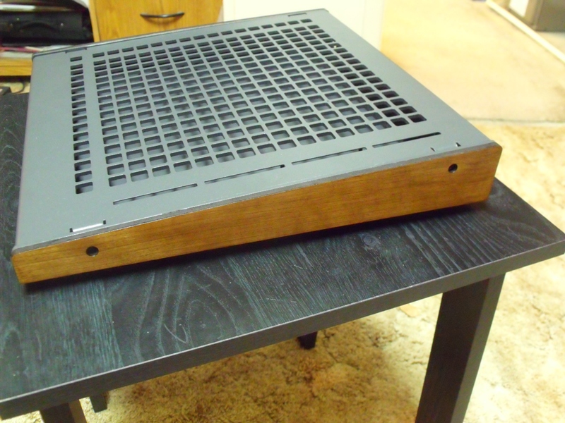
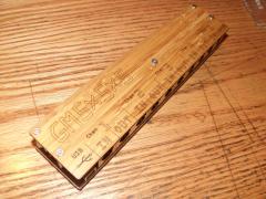
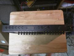
And wood is done:) I'll post the file if anyone wants it

-
we got wood :)
-
CAM expert but it's the same type of enclosure as Front Panel Express/Schaeffer offer. They do all the infill
-
that's everything. In hindsight, I wouldnt do the blind studs again, the accuracy of those was a little on the loose side and required some board convincing to get right, that would have lowered it $35
-
$300
-
-
-

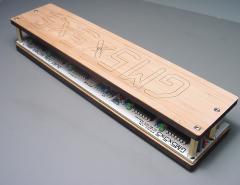
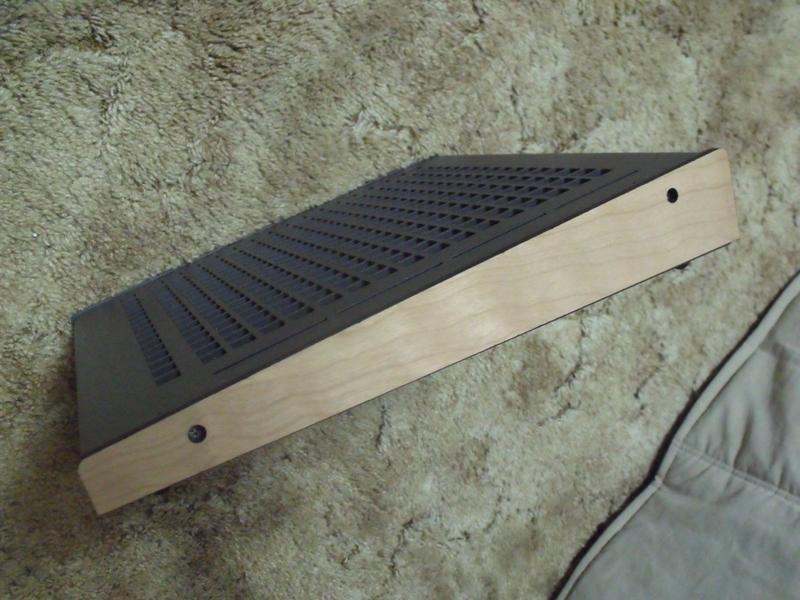
From the album: Altitude's pics
Slim case! -
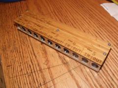
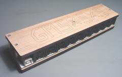
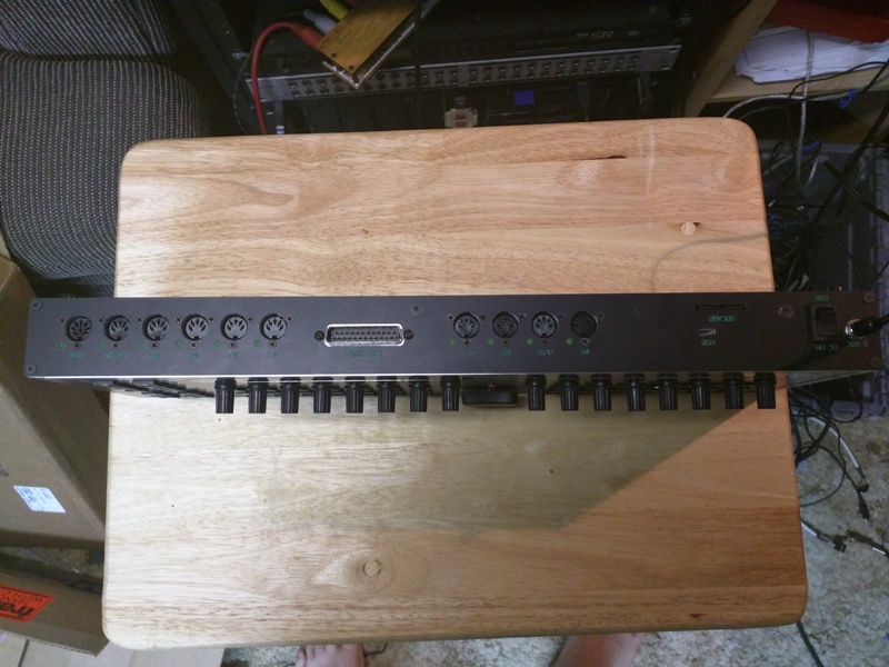
From the album: Altitude's pics
Slim Case Back! -
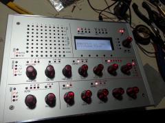
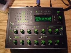
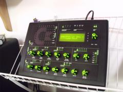
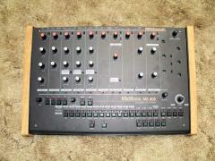
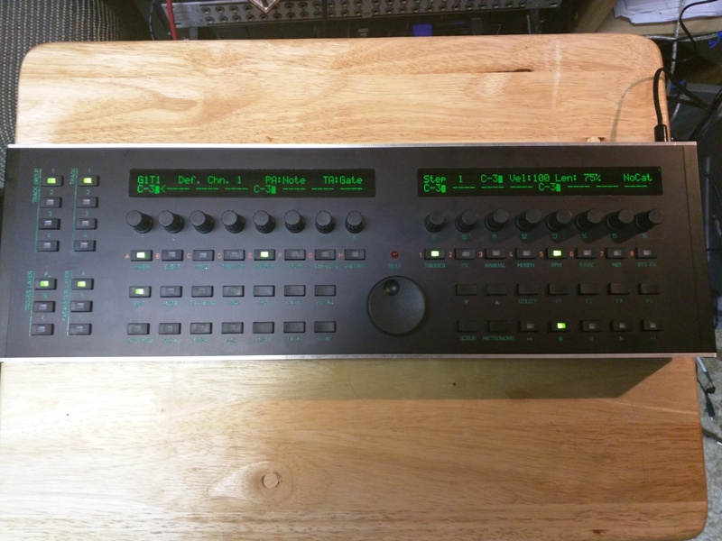
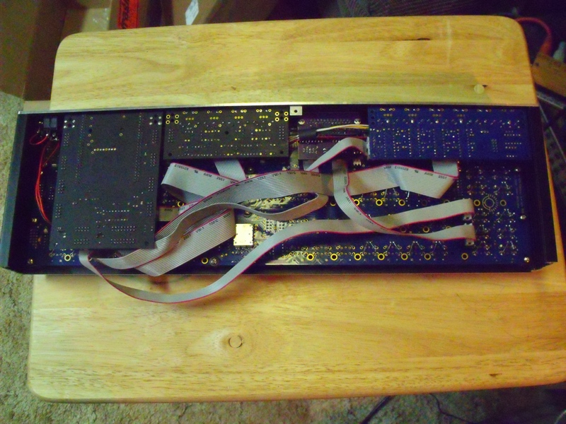
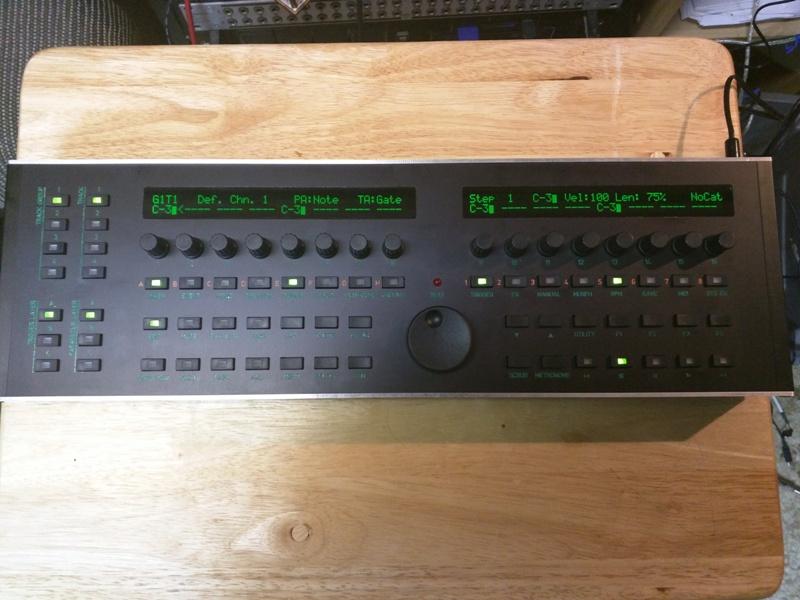
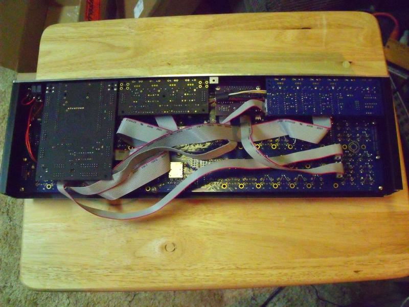
So I've been had this in the planning stages for a couple of years now and with the advent of the line driver and BLM, now was a good time as any so I got it done. So this is: STM32F4 core 1x midi IO 1x Line Driver 1x quad IIC (BLM ready) I used the 3F Mec parts for the backlit buttons and hand wired LEDs (not that fun), Worked out well, it would be nice to have a rev of the CS board that does have them wired up, the other foot print does and the MEC footprint has the holes but they are not connected to anything all in a nice 42mm thick CNC case Total current draw: 300 mA

-
So I should be able just to use the out on the Midi i/o correct? so J11->midi I0-> Quad IIC BLM connector
-
So just to confirm: quad IIC blm port connects to J5B on the STM32F4 core?
-
Perfect. Thanks..
-
Question to anyone who's finished: whats the max current draw?
-
BLM 16x16+X PCB and case order [CLOSED/waitlist]
Altitude replied to latigid on's topic in Bulk Orders
sweet. Looks like laser cut wood sides time (make it sound better) Is there a drawing of the case? I need the side profile only -
Hows this supposed to work with no cutout for the LCD? Those mainboards are made wrong.
-
"I wish I had a tact with a longer actuator" solution
Altitude replied to Altitude's topic in Tips & Tricks
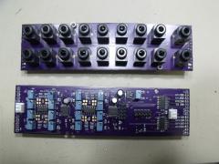
well not necessarily, the standard height with the tact and rectangular cap i show above is about the same as the TL1100 the the stock switch cap but if you need more (say you want to put a standard LCD under the panel, you need at least 14mm between PCB and panel for it to fit) you just add the spacer between the cap and the switch. There is a hole down the middle so the light still works fine. It's always been a struggle to find buttons tall enough for a control surface where the LCD and all the controls are on one board and not have the bezel of the display poking out since the buttons are too short (i.e. Shruthi, P6, PreenFM etc). Personally, I cant stand the way that looks but there really weren't any options since everyone used the same tact switches -
Good idea but those are a but on the small side
-
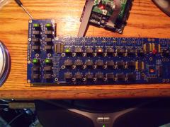
I figured they would be useful for someone STMF4 Core cutout. This requires a 2mm washer to go between the threaded terminal (mouser PN 534-7700) and the panel since the discovery board and core board do not sit in the same plane. This also recesses the SD card somewhat but seeing that it does not get removed often, I opted for a small slot for aesthetics instead of a bigger opening to make it easier to get out For the midi cutouts, you want to use SDS-50J midi connectors (http://www.cui.com/product/resource/sds-xxj.pdf) which have holes in them for M2.5 or 2-56 screws. The holes to the right are for activity LEDs stmf4CoreCutouts.fpd 4xIIC.fpd midiIO.fpd
-
I'm down for 30 clear and 10 data wheels
-
What about the 20k parts
-
woops, sorry. Too many blm threads. I do have the PCB back on topic: re: bat54/NPN So you just stack the diode on top of the transistor?
-
Did you ship everyone's PCBs? I expected to get mine with the case