

Altitude
-
Posts
1,184 -
Joined
-
Last visited
-
Days Won
30
Content Type
Profiles
Forums
Blogs
Gallery
Everything posted by Altitude
-
Not to pour cold water on you or anything, but what you are proposing involves the complete rework of the MB808. None of the controls on the MB808 are digital beyond the tempo knob, they are all direct analog controls. To add digipots, you would need to relay the board and a complete re-write of the firmware and to port it to the new core since you would be looking at hybrid SEQ/MF device (which no one has done and would probably require a TK'ish understanding of MIOS to do successfully). To put things in perspective, the original MB808 took Jeff about 2 years to design, then a team of about 30 ppl about 6 months to work out the bugs in the prototypes and software optimization. There were 3 revs of boards. The kicker to all that is that ALL the info and documentation from the 808 forums was deleted so you would be starting from scratch from the orignal 808 schematics. Also keep in mind that Doug has yet to deliver a single board to anyone despite it has now been almost 4 years since he started taking orders and if you happen to have one of the original 3 rev boards, all the documentation for those is history If you absolutely must have external control of certain parameters (which I dont really see the usefulness of), I agree with Nasrudin, tap it with a CV
-
not yet, but there isnt anything there that would make me think it wont work.. I mainly chose it for the mounting holes on the side so it can be easily mounted with L brackets to a panel
-
No, not that app specifically but it's not really a software thing but a persistent issue with running long serial lines across any app.. Look at the LPC17 Schematic and see how the J8/9 lines are buffered
-
not sure software will fix it, serial lines can only be so long before the signal degrades. The drivers on the LPC core will only go so far.. I had problems with 2 hops so I am sure you will start seeing it with 5 or 6
-
I had a similar problem on my SEQ and a buffer fixed it. I just added a small daughter board in the chain with a 541 CMOS part
-
those are the Kyocera ones (formerly Optrex)
-
 he's talking about the 4L not the full seqV4, there were no metal cases that I know of ever made for that. There were a couple acrylic designs however and it should be fairly straight forward to engrave braille with a laser. I have some prototype LED backlit laser cut buttons being made right now, obviously the LED part is of no concern but they are designed to fit the 4L mini tact switches and you can make them any shape (or any engraving) you want
 -
files added..
-
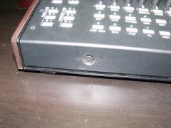
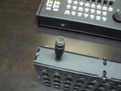
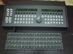
This is based on Ilmenator's 16x4 BLM PCB that he was kind enough to let me liberate from him and a matte Ponoko laser cut case. I used the same LEDs I used for my SEQ and they match perfectly brightness wise. I interfaced it to the CS via a mini din8 connector which needed to be buffered to work properly (thanks to TK). I'll post the files for the case and the brd and schem of the buffer I used (I obviously just did it by hand here). Thanks to Ulrich and Throsten for another great project! These are the files for the case, please note that there is NO HOLE for the connection, the location and size of that will depend on how you want to implement this so its up to you. Standoffs were 8mm for the top, 18mm for the bottom. I ended up grinding the 18mm ones for a tighter fit so 16mm plus washers may be a better choice to make up for tolerances http://misw.us/p2_blm_case.svg Here are the sch and brd for the buffer. I designed it to simply attach to the board via female DIL on the back like I have it on my PCB. I have NOT actually made these yet so you probably want to check it for any errors but it is simply based on the connections shown the LPC17 schematic and is how I wired my hand made board. Also worth mentioning is the DIN8 socket and DIN cable I used despite having the same colored wires, did not have those wires connected to the same pins so make sure you check with a meter..
-
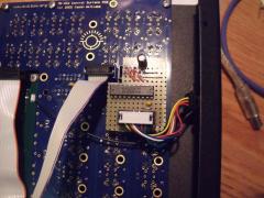 Serial line buffer
 -
Illminator's BLM board stand alone addon
-
-
From the album: 16x4 BLM Peripheral
-
From the album: 16x4 BLM Peripheral
-
From the album: 16x4 BLM Peripheral
-
From the album: 16x4 BLM Peripheral
-
heh, His village has a population of 1.3 million ppl (Moore is metropolian Oklahoma City :) Esher, try the IRC channel, he's there daily
-
+1 There is no analog side here so the cheapest, crappy, cell phone charger will be plenty. in fact, all you need is a cell charger + a USB B connector and you are done the PSU for the SEQ
-
success! I'll branch this thread with all the case and design files :smile:. Now its time so see how long I can go I suppose I should patch in J19 for a complete solution..
-
Ok, This should be correct now:
-
Thanks, that helps a lot. Have not even looked at the LPC schem (still on the STM core), Will revise Just so i have this clear in my head, SI is the input back to the core for the DIN, correct? This is my problem, the DOUT functionality works fine, the DIN stuff does not though so I figured that pin would need buffering
-
Can I get a quick opinion of this quick and easy board and schem?
-
perfect, already have some from the level shifter. so my premise is correct then, buffering the din should get me more length? That was the chip in the breakout box you had a pic of correct?
-
I have Illmenator's 16x4 BLM up and running and now am looking at adding it as a peripheral to my SEQV4 but I have run into a problem, the length of the leads I need for it to work is VERY short and the way I was planning on deploying it was to use a Mini DIN8 connector and cable. I can get it to work fine with a short length of ribbon cable but when I use a similar length DIN cable, the DOUT stuff works fine, but the buttons do not work reliably. I have the shield of the cable connected to ground. Would a viable solution to fix this be to buffer the serial output from the BLM? Would this work the same way as buffering a midi signal (hex inverter)? Any input would be appreciated..
-
My advice: Bite the bullet and just cut all the jumpers to length by hand and make sure you use 24 ga wire with FLEXIBLE insulation (i.e. NOT TEFLON), it takes a while but down the road it will save you a TON of time. The 0.1" ribbon is a pain to strip and if you break any of those leads, you have to make a new one and take out the old on to fix it (had to do that twice) which is a long and painful operation. With single wires, if anything goes bad, its ONE wire to replace
-
Sure. I recommend you add a SPDT switch with one leg connected to J1, the middle pin to J2, and the other leg to your PSU. That way you can easily switch between external power or USB power. Handy to have and will prevent you from using both at once accidently
