

sneakthief
-
Posts
374 -
Joined
-
Last visited
-
Days Won
8
Content Type
Profiles
Forums
Blogs
Gallery
Everything posted by sneakthief
-
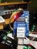
I have an STM32F4 that refuses to work with both SD & ENC28J60 ethernet modules using MIDIbox NG & CV V2. Working: Ethernet and no SD When I boot it without an SD inserted, the ethernet works fine: Ethernet cable connected: yes Ethernet MAC address: 00:39:36:30:39:31 Ethernet services running: yes DHCP: enabled IP address: 192.168.0.100 Netmask: 255.255.255.0 Default Router (Gateway): 192.168.0.1 Not Working: SD and ethernet together (ethernet gets disabled) However, the moment I insert an SD card, I get various errors and the ethernet disconnects: [MIOS32_ENC28J60_PackageReceive] glitch detected - Ptr: ff09, Status: 7fb8 (max: 05ee) cd7f or [MIOS32_ENC28J60_PackageReceive] glitch detected - Ptr: ffff, Status: ffff (max: 05ee) ffff Working: SD and no ethernet If I boot with the SD card inserted, the MAC address is recognized but the plugged-in ethernet cable isn't detected (which could be due to another error): Ethernet cable connected: no Ethernet MAC address: 00:39:36:30:39:31 Ethernet services running: no DHCP: enabled IP address: not available yet Netmask: not available yet Default Router (Gateway): not available yet When this happens, my router actually recognizes the ENC28J60 and assigns it an IP address. Here's my cheap-o eBay ethernet adapter:
-
Glad it worked out - when I find out what's wrong with my toolchain, I'll post the latest version. The problem is that I have 4 (!!!) STM32 toolchains running and something is conflicting: MIOS32, Spark Core, Mutable Instruments & Axoloti.
-
Heads up: this is a currently big issue for anybody wanting to use OSC over ethernet with projects like MIDIbox CV V2. When the SD card is inserted, the ethernet module doesn't function! Seems I have a different issue here than I originally thought. Taking this to a different thread.
-
BTW, here's my hardware config for using 1x LRE8X2 connected directly to J8/J9 and all the other DINs/DOUTs chained after it (first a DINx4 for the buttons then a DOUTx4 for the clock/gate outs) MBCV_HW.zip
-
Mike Pig: I think I have a compiler issue with the MIDIbox CV2 firmware I posted - here's an earlier version from August that works fine. project-cv2-8_30_2014.hex
-

OSC-Capacitive Multitouch + Raspberry Pi (no tablet Topic)
sneakthief replied to Phatline's topic in Miscellaneous
FYI - USB to Ethernet adapter for Android: http://www.ebay.com/sch/i.html?_odkw=usb+the+ethernet+android&_from=R40|R40&_osacat=0&_from=R40&_trksid=p2045573.m570.l1313.TR0.TRC0.H0.Xusb++ethernet+android.TRS0&_nkw=usb++ethernet+android&ghostText=&_sacat=0 http://www.amazon.com/BobjGear-Ultrabooks-EXCEPTIONS-Description-Included/dp/B007RTACDM -
New Crop of Sequencers... What do you Think?
sneakthief replied to cosmosuave's topic in MIDIbox SEQ
-
Oh, I see what happened - the English used in the second sentence is somewhat ambiguous: "Also I was expecting to use ilmenator's SCS but it connects to J8/9. Is it possible to get it work with two LRE8X2 ( TK ? )" I thought he was asking if it's possible to 1) use your SCS and 2) to get MIDIbox CV2 to work with 2 LRE8X2.
-
The LRE's are just chained on J8/J9 while the SCS is on J10: DIN/DOUT (buttons, LRE, Gate Outs) - J8/J9 (MBHP_CORE_LPC17) - J8/J9 (MBHP_CORE_STM32F4) SCS buttons & encoder - J10 (MBHP_CORE_LPC17) - J10A (MBHP_CORE_STM32F4) More info here:
-
Did you miss TK's post above? "Meanwhile two LRE8x2 are supported (max!)"
-
:double post:
-
Did you try plugging the LCD into the other connector? It's supposed to be in J15a. Since MBSeqV4 uses both LCDs, maybe you have it in the wrong one? Not sure about the SD card problem. I didn't notice any errors when I compiled it, but who knows.
-
I just compiled the latest source, uploaded it to the core and verified it with the MIOS terminal, but didn't check the LCD - so maybe there was an issue. The soonest I can check it is in a week.
-
MikePig: here you go - http://sneak-thief.com/MIDIboxNG/MBCV2-02-02-2015.hex
-
Just a couple more in-progress teaser shots. It's going to be a while longer because I don't have much time in Feb. To do: a few more front-panel holes to carefully counter-sink (thanks for the advice FFWD!), lots of internal mounting to finish with ...namely the button boards. And finally, lots of soldering to do (DIN, DOUT, Line Drivers, OLED's, buttons, the whole CV panel, etc.) For the CV-section, I chose: - 8 CV - 8 Gates (with LED's driven by the DOUT) - 8 CV In - 5 Clocks (with LED's driven by the DOUT) - Run/Stop - Clock in Notes on the interface: - 8 buttons to choose which CV channel you're working on - 4 buttons to choose the OLED and its parameters - Start, Stop buttons - Record/Save patch - Fast-forward: fast shift-key for when turning the encoders - Patch +/- - Encoder Bank +/- - 4 assignable buttons (I, II, III, IV)
-
latigid on - yes, I know there's a dedicated clock pin :) I was just curious if I could use the analog inputs instead.
-
TK: Is the separate clock input wire still necessary if you also use the Analog Inputs and assign them in the matrix?
-
No, you read it wrong: mfk wanted 2 pairs and I only shipped him 1. Therefore he requested one more pair. It appears all ten orders from blingy's batch are now accounted for.
-
Thanks for the tip, Altitude! I was nervous about using that method because I didn't trust the tolerances for them to match up exactly. In fact, as I mentioned, that's the problem I had with the "friction bumps" I added to the windows: they should have extended quite a bit past the outline of their respective hole - but they didn't.
-
mfk had asked for 2 pairs and I only noticed it later and was only able to ship him 1 pair. Consider this a request on behalf of mfk for the last pair. He'll confirm, of course.
-
novski: I used Formulor.de here in Berlin for this massive order (P3-sized matte black and P1-sized middle-grey transparent). The only thing I'm not happy with is that I thought I had big enough bumps on the transparent windows to be able to friction-fit everything - but somehow the tolerances weren't as good as I expected and so I had to add small (but not visible) shims to hold them all in place. Luckily no other "errors". I'll correct the SVG files before posting them here.
-
You could of course - but I don't find it aesthetically pleasing to see PCB and all the other junk beneath the surface.
-
Ungleichklang: Lemur is really the way to go here. No need to reinvent the wheel - and think of all the time you save by using TK's pre-built interface. Re. my build progress: (I was pretty ill this past year... found out I have a genetic mutation (Gilbert's Syndrome) that makes me sensitive to chemicals, especially soldering :-/ However, I have an excellent soldering-slave who happens to be my spouse :D) Anyhow, I just got my Formulor order and will soon have pics to show of my MIDIbox CV2 case :D :D :D FIY, the case at Formulor.de cost 67e and the optional smoked-gray transparent windows were 17e. All the windows aren't necessary if you place 256 holes in the front panel, but I'm sure the price will end up being the same. I'll post all my design files, BOM and notes in March.
-
And here they are, a month early :D NOTE: Please send me a PM (private message) with your address so I can calculate each invoice. I'll send you my PayPal (or SEPA bank details)

