napierzaza
-
Posts
442 -
Joined
-
Last visited
Content Type
Profiles
Forums
Blogs
Gallery
Everything posted by napierzaza
-
MIDIbox of the Week (MIDIbox FM of Napierzaza)
napierzaza replied to napierzaza's topic in MIDIbox of the Week
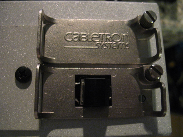
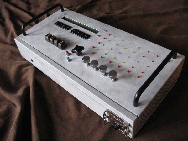
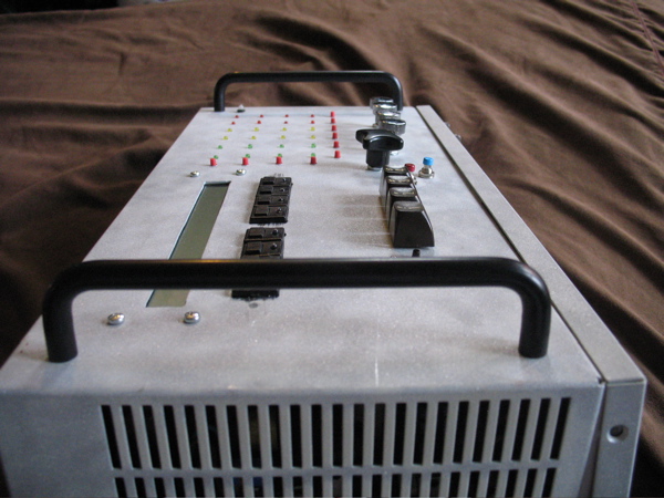
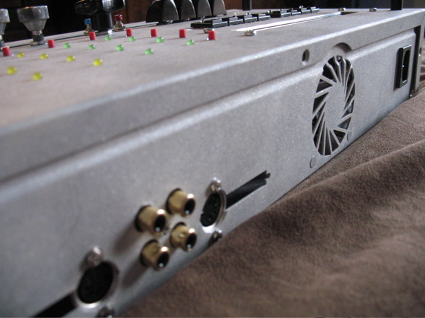
Cabletron I believe, ooooold. Still says it too (see below), right in the lower right there were those holes for different inserts (coax, ethernet, fiber) and I managed to get one blank, and an ethernet one. the ethernet one fits the Commodore 64 switch quite nicely. I managed to nab a bunch of these cases before my co-worker/scrap junker managed to grab about 6-12 of them and sell them for their aluminum. I think it was a real shame because the cases are very nice. My next project, a midibox SEQ, will be made with a yellowed, unpainted Cabletron box. The anodized black handles are from a separate old Cabletron PSU. I like to use a lot of recycled parts, it's cheap and adds some style. I think I might have to make a nice looking panel for the LCD, 8-select buttons and the 4 commodore buttons, because it looks a little plain otherwise.
-
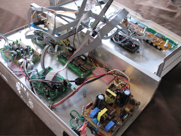
Okay, this took a while for me to do, but it's finally finished, well almost finished. I just have to figure out how to upload the FM application and figure out why in this setup the PIC isn't working (not sending out a MIDI message). Anyhow this is it, recycled aluminum case that I sandblasted so it's all pitted. Lots of recycled knobs that are really nice and high quality, and even some recycled C64 buttons for good measure.


-
MIOS Studio can't find my USB MIDI Device
napierzaza replied to napierzaza's topic in MIDIbox Tools & MIOS Studio
Do you happen to know which are which? -
Return of the MBHP USB Question (SOLVED)
napierzaza replied to napierzaza's topic in Testing/Troubleshooting
Oh, okay, but it did say to upload it just like an application correct? I will try Midi-ox. -
How senstive is the FM? will a .1 volt difference make or break it? I appears as if my PSU is slightly above 5v.
-
Argh, well I found a really god PSU that has 12+, -12, and 5v (2amps). It would be really hard to have two PSUs in the case that I'm working on, this one fits perfectly and seems to give good voltages. Anyhow I can't really power it using J2 can I? I have my FM on there. Is it any different to hook it up via the holes left by the 7805 once I remove it? My limited experience in electronics says no, because it's still pretty close to that capacitor... but...
-
MIOS Studio can't find my USB MIDI Device
napierzaza replied to napierzaza's topic in MIDIbox Tools & MIOS Studio
I see it now, it's in the MIOS Studio page. "Mac user may want to download PlumStone to ensure that Java can access the MIDI hardware on their system" Didn't really sound like it was essential. Thanks Stryd. -
Okay. So now I have a M-Audio UNO, and Core programmed with MIOS 1.9d and I'm trying to setup my 24lc64 eeprom with the MBHP USB software. So here's what I tried: It says load it with a non-bankstick program to upload the software, so I upload MIDIo128 because there is no reference to Bankstick on that page. It loads up fine to the PIC. After that I connect the eeprom as if it's a bankstick (j4). I then have to rename the .syx file to .hex because the instructions say to load that file via the hex upload. I do this and upload the file. MIOS says everything is fine (though it gives no error when nothing is attached anyway). The USB module still can't be detected as a MIDI interface in either MAC OS X or Windows. I also used Serge's Sys loader and it also basically failed (no errors but neither Mac nor PC detects). Are there any details I'm missing this? Are there alternative ways to program the eeprom using MIDI/MIOS Studio? Can I program the eeprom by connecting the USB module using J11? The (brief) directions say connecting as a bankstick but I thought that I might be able to use J11 but I'm not sure on the setup or if it would work any better/at all.
-
MIOS Studio can't find my USB MIDI Device
napierzaza replied to napierzaza's topic in MIDIbox Tools & MIOS Studio
Ah, it works now. Strange, didn't see that in the newbies MIOS upload page. -
MIOS Studio can't find my USB MIDI Device
napierzaza replied to napierzaza's topic in MIDIbox Tools & MIOS Studio
Okay, tried version 7_5 and it still didn't work in Mac OSX. Works in PC though. -
Okay, so I have a M-Audio UNO and Reason detects it fine in Mac OS X 10.4.9. But when I run Beta 7_4 of MIOS Studio I get nothing detected. Is there any known issues such as this? Should I use a PC? I read somewhere it works with Mac but it doesn't appear to. I didn't have drivers installed for the device, but did find some once it didn't work automatically with MIOS Studio. But it still doesn't work in MIOS studio.
-
I have a 5V PSU that works up to 2 amps. I'm trying to hook it up to my core but I'm not sure I'm doing it correctly. Basically I'm just putting the power to the power pins (right before the rectifier). For some reason the measured 5v suddenly goes down to <2v when it's plugged in. I just setup a core module where I just took out the 7805 and ouf pins for connecting power into where the IC was. Is this okay? I suppose it's a regulated supply as it's 5v consistantly (I can't find a 7805 on the board, maybe a similar chip is present?).
-
Thanks. You don't happen to know the other answers do you?
-
Seriously does anyone know? Just point me to a document if I missed one.
-
I'm a little confused on how the midi in/out jack situation works. Basically, how does the number change according to what modules you have plugged in. Okay so the CORE has 2 ports, 1 IN and 1 OUT (unless you have the unreliable out of a 4620?). If I added an IIC module I'd get 2 more. But what if I add a USB module? Do you get 4 more or just 2 more? From where? The diagrams in the USB page mark some of the ports as "Allocation by MIDI link" but I'm somewhat unclear on it. Does that mean if I use the USB module I'll still only have 2 MIDI ports, and IN and OUT from the USB module (in2,out2)??? Will I still be able to use the ports on the core module or the first IN and OUT of the USB Also I noticed that the FM has a "through" port on the back panel. Is this just a passive port mirrior to the out connection?
-
Arg, I was going to make a 1bitgroovebox but it completely failed. I built an Atmel ISP and it never ever worked out, I tried it on a lot of computers but it just failed everytime. It wasn't my parport because I burned a PIC using that parport. I even built a whole bread-board for my 1-bitgroovebox but it was all for nothing. Big waste of time. Planning on building a ring modulator next.
-
Mine is completely working now, so it's all you should have to do to make it work.
-
I'm interested to see the values of these chips. I have 3 opls and 2 yacs (yes, the extra opl is scrap). I also have an FM board from smash I might populate and SMD solder and see how much that is worth.
-
Okay cool, drop me an email
-
It also looks like PonyProg programs them, but I don't know if a direct connection (ie no board with caps and resistors,and buffers ) will do or not. I'll take a look at your link. I'm located in Montreal Canada, where are you? It's getting warm up here! I've only tried connecting it directly, also I've tried it with and without the eeprom connected. ... I'm an effects pedal?
-
Dunno, looks like it was, but somehow it was interfering with the circuit. Like I said I couldn't find any pinning that make it work. Strange that it disabled everything else, would have thought it would only affect things after it and not things (voltages) before. Thanks again for the help BTW.
-
Unless someone knows how to write to an eeprom using jtag?
-
Okay, well I guess this isn't happening. I'll go buy an M-Audio device.
-
Okay, so now I've wasted about 4-5 hours with a Windows 98 installation that didn't work. It appears that OSX sees it as the right vendorID and productID but any windows version sees it as 0000 0000. So I added a line in the .inf file that says anything with 0000 0000 should be loaded with the driver. It "worked" in that the driver is actually loaded onto it, but the control panel sees nothing at all. Here's the best question ever: Thorsten, CAN I JUST BURN MIOS (NOT JUST THE BOOTLOADER) ONTO A PIC AND THEN UPLOAD THE SOFTWARE ONTO THE USB MODULE SOMEHOW THROUGH THE CORE? I don't know if burning MIOS actually works, so let me know.Also you only inferred a little that the USB firmware could be programmed in such a way. Please let me know.
-
Success! After making the above changes the Programmer (reverse LED, ground pore (Jidis did it for me), and jumpering R8) was still not being seen. Than I decided the scrape all the traces that were near other traces and when I plugged it back it in worked. Not sure why though, unless there was some unseen short. But anyhow it was seen and my PIC is now burning, but it's on the slowest setting and looks like it might take an hour or so. Next I'm going to install Window 98 somewhere and try and get my USB module working. Thanks Thorsten, I think this proves my ISP Atmel burner was have troubles for reasons other than my LPT port.