latigid on
-
Posts
2,524 -
Joined
-
Last visited
-
Days Won
149
Content Type
Profiles
Forums
Blogs
Gallery
Everything posted by latigid on
-
Are you measuring the correct DOUT pin? Remember that they're mirrored.. You'd need a scope or logic probe to read the SC/RC/SO data pins correctly. Can you connect to a known working Core and use the MIOS command test_DOUT pin (I don't know the correct method for this, you have to search yourself). For DOUT without AOUT, :whistle:
-
Are you sending notes on the correct AOUT channel? I haven't done this by the way, I have the old system with a level shifting solution.
-
-
Hi, this should hopefully work (TK's words not mine...) CV_GATE_SR1 3 That should send the gates to the first SR on the DOUT. Good luck! Andy
-
Indeed, you can see the PCB traces here: http://www.midibox.org/dokuwiki/lib/exe/fetch.php?media=wilba_mb_seq:wilba_mbseq_pcb.pdf
-
Use the adjacent header to daisy chain the next series of shift registers through a new cable. They're the chips on the DOUT in fact.
-
No worries, and there's no hurry for major changes This was my idea for a 2-3 rack unit front panel for the SEQ: MBCV would be similar but with CV inputs and clock outputs for the right hand connectors.
-
I think in combination with a BLM, having the ability for each track to send its own gate would be a powerful feature. If a gate event is already defined in the SEQ then it would be great to assign this event to an arbitrary DOUT pin if it's possible. Even if this repurposes the 64 available gates/triggers on AOUT channel 16 gates -- I'm not sure if anyone is using this feature ( ?) Many thanks, Andy
-
No extra CV needed :) Okay, but what's the best implementation? Assign all tracks to AOUT port, channels 1-16 with duplication for 8 channels to the respective MIDI ports? In this case there's nothing in the config file to assign the gates to the correct SR (AOUT 1-8 but not 9-16) But isn't AOUT 16 already configured for extra gates with one sent for every MIDI note? Going back the other way, using the respective ports with duplication to AOUT 16. But here wouldn't the gate respond only if it hit the correct MIDI note? Would there be a way to map all notes of a channel to a single note on AOUT 16 and thus the correct SR pin? Many thanks,
-
Feature request: all 16 tracks can have their gates assigned to DOUT pins. I think at the moment just the AOUT + extras on "AOUT_16" can send them. I'm not sure how that would work with port assignments: can a gate be sent on both a MIDI channel and as a DOUT signal?
-
Right... you want to use the GPIOs for gates. Did you enable this in your hardware file? # should J5A/B/C outputs be enabled (0: no, 1: yes, 2: yes, but in open drain mode)? # - the 6 first AOUT gates will be forwarded to J5A/B # - the remaining last 2 AOUT gates are available at J5C.A10 and J5C.A11 (LPC17: J28.WS and J28.MCLK) # - DIN sync clock will be forwarded to J5C:A0 (LPC17: J28.SDA) # - DIN sync start/stop will be forwarded to J5C:A1 (LPC17: J28.SC) # - if open drain mode enabled (option 2), external pull-ups have to be connected to J5 pins # (advantage: pin levels can be pulled to 5V) # # NEVER USE THIS TOGETHER WITH ANALOG POTS - IT WILL CAUSE A SHORT CIRCUIT! J5_ENABLED 1 The idea I think is to move towards DOUT gates, I suppose the pin assignments from the Core remain as a legacy function. P.S. Open-drain mode does not work (at least for STM32F1 and I think LPC 17), your gates will be 3-3.3 V and no protection is implemented for the Core. Take care how these are connected!
-
Hi, you shouldn't need use a CC, just enter some notes into the pattern. Hope that works!
-
Hello, you should configure your track as AOUT channel 1, this should send the gate. It would be great if TK could tweak the SW to allow all 16 channels to send their gates to the DOUT, I think with the BLM this will be really cool even if the corresponding CV is not sent.
-

Pull down resistors for banana plug inputs to AIN
latigid on replied to widdly's topic in MIDIfication
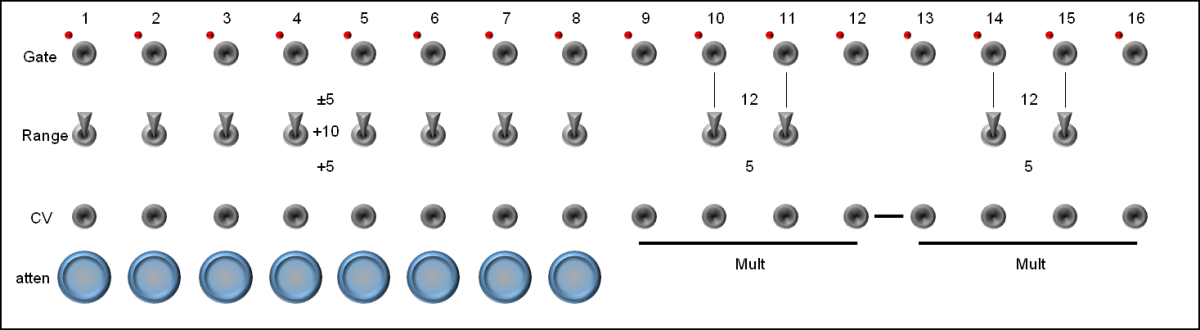
First thoughts: The 1M resistor will create a voltage divider, I guess you chose 1M to minimise the effect of this. Definitely go for Schottky-type diodes for clamping. You're correct in that the reverse voltage will kill your IO otherwise. You might want to check this out: It's designed for an STM Core but could be easily adapted for PICs. The concept is to use a rail-to-rail opamp as a second inverting amp stage instead of diodes. There's no chance that a higher voltage gets through unless it manages to raise/lower the power rails (unlikely in a modular setup). The design has input attenuators and switches/jumpers for selecting the voltage range (unipolar 0-5, 0-10 V or bipolar -5 to +5). I might have some spare boards available, currently I haven't tested them due to other commitments. Let me know if you want some and I'll look into it for you. -
Full 16x16+X BLM with silicone buttons, matching case. Interested?
latigid on replied to latigid on's topic in MIDIbox BLM
Let's keep up the discussion, I have an opinion but it's not meant to trump anyone else's. For me this would look a bit tacky and lose stability. Maybe wooden end cheeks could be added but here I think a sloping sheet music stand would be the best option. I'm trying to picture this, but if I've got it right you suggest standoffs on the rear of the panel. If you read up a few posts my idea is to use long studs (threaded rod) on the rear of the panel, through an acrylic spacer and then through the PCB and tightened on the back. This comprises a lot of material to avoid flexing and the threads are smaller in diameter compared with standoffs. I've kept in the other mounting holes on the PCB (2.8 mm), so if more strength is needed they could act as fixing points on the back. But in this case you couldn't go through the spacer as there's not enough material left for the grid shape after the hole has been cut out. In terms of flat or sloped, we have to consider what else goes inside. Will everyone buy a miniCore board? Or do some prefer to use their old Core8s? What if others would like to develop a BLM-specific instrument e.g. with a Core32 inside? Again, I need to check the full PCB dimensions but a square case will have wasted space at the bottom of the BLM. In this situation what is preferred? A flatter part at the front or a uniformly thicker case? This is my main motivation for a sloping box. You're dead right, U-shaped cases are much cheaper than the "Consolet" style from Protocase. EDIT: but in fact the "sloped top" style is the same price as the U-shape. The "consolet" has an extra flat part on the top and a removable rear panel. So there's already savings available. -
Full 16x16+X BLM with silicone buttons, matching case. Interested?
latigid on replied to latigid on's topic in MIDIbox BLM
Also a possibility. Just a question: is your idea motivated by aesthetics or price? From what I've seen of Monomes and the like, the flat surface is not very ergonomic, hence my idea of a slope. It can possibly be made flatter but I have to check the PCB first. Also remember that we're already talking 30 cm+ for to the back of the case, bigger than say your Novation controllers. Didn't you already put four together? How is that to play? -
It looks that way but thankfully the socket doesn't go right to the PCB surface. Check a Core8 or on midibox-shop.com and you'll see.
-
Heh, nothing too fancy! I'm still learning PCB design, but one rule of thumb is that you shouldn't have breaks in your ground plane where signals run across. If they go over a slot the return current has to take the long way around. Probably complete overkill unless you're getting into the MHz range, but I figure why not if it can be done without too much fuss. The blue is a keepout zone as measured from the Core r4,
-
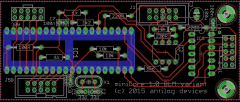
© 2015 latigid on
-
Thanks for having a look, I will move the resistors away from the edge of the DIP40. I always put caps as close as possible to the power pins for the best effectiveness. Some 4-wall sockets are actually mirrored (we're looking at the back of the board). It's always best if you don't have to, but bending components out of the way or putting them on the other side of the board is always possible. OSHpark won't be too expensive so I'll order a couple after a few changes.
-
and done I think. All 16 mil/single sided, I should check the clearances inside the DIP40 socket. I put in J5B in case anyone wants some extra pot/CV sources.
-
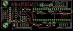
© 2015 latigid on
-
Great, will do!
-
I'd like to redesign the Core board to fit with my There are quite a lot of unused connectors and components. I will add a line driver (74HCT125) to buffer the IO. First question: are pull ups on the unused pins still recommended?
-
Full 16x16+X BLM with silicone buttons, matching case. Interested?
latigid on replied to latigid on's topic in MIDIbox BLM
I don't have an exploded view yet but perhaps I can explain in words. This assumes an enclosure from Protocase Designer. Front panel is 3.2 mm aluminium (8 gauge in the US). There are 15 mm M3 studs running along the top and bottom edges and an M2 thread in the middle. I haven't yet specified the extra north-south studs as it messes with the symmetry :). Next is a 3 mm acrylic spacer which extends from the left edge to the sliders. It provides a semi-rigid support to keep the buttons in place, especially the extra ones that need to be cut into 1x4 pieces. Then the button pads. They have a 1.75 mm skirt and the buttons themselves are 10mm on top. This gives about 4 mm clearance over the top panel, more or less the same as ADAfruit's UNTZrument. Then the PCB (1.6 mm). Note that the sliders are 7 mm tall from the top face of the PCB. The back of the 3.2 mm panel must be milled out ~2.2 mm leaving 1 mm panel space to fit them under. The studs would pass through the PCB and be fastened with washers/nuts on the other side. The M2 screw right in the middle is important as it provides an opposing anchoring force. If more stability is needed there are four M2.5 (?) holes for each set of 16 pads. I hope the PCB+spacer+panel will keep everything rigid though, especially if it's all flush. (-1 point for JBweld, the glue would get in the way here) Then either a standard Core8 or a mini one as a piggyback module. Wire to the DIN 8 and you're done!