latigid on
-
Posts
2,524 -
Joined
-
Last visited
-
Days Won
149
Content Type
Profiles
Forums
Blogs
Gallery
Everything posted by latigid on
-
From the album: Mech SEQ
© 2016 latigid on
-
From the album: Mech SEQ
© 2016 latigid on
-
Sorry, my terminology is confused. Jog is the encoder, shuttle is the side part. Right, I remember it may have been a pot element to measure the acceleration.
-
Sure Lost you there. For reference, these are the switches to be used -- no diode mounts, no external plungers. Could work, at a risk of having long skinny PCBs (prone to flex). Current design has some standoffs matching with the base PCB, they just can't go up to the front panel. This is more or less what I thought, except no mounting to the front panel. If this is the case, we could even think about a much thinner steel panel, making the LCDs/OLEDs prettier ;). As it is. there's almost no room on the "southern" edge of the front panel. The switch caps go very close, so the only place for standoffs is slightly further in. With luck, there'll be no problem with many standoffs anchoring the base PCBs, as the only thing left to consider are I2C (PIC only) modules. unless I'm not following you properly, this is a contradiction? Either you have lots of "internal space" (underneath the Base PCBs), or you have lots of mounting holes filling that space. Lost you again. The "plate" is nothing more than a fibreglass PCB with cutouts to hold the switches, and through hole pads for encoders, aux switches, a few LEDs and sandwich header pins. Are we on the same page yet? Heh, of course :). I actually have one salvaged one from an old controller. They're friggin massive though, and I've never understood the handling properly. Does the jog part have multiple switch contacts that close in sequence?
-
I don't entirely get it, Poker 2 still has a switch plate. Also Cherry MX switches have the central mounting post and, if not plate mounted, two plastic stabilising nubs for the PCB. Matias have merely two through hole pins, so need some stabilisation. Likely it'll still be a bit wobbly. The encoders and aux switches need to be elevated -- the keyswitch + cap is more than 20mm tall, but the encoders have a usable dimension of about half that. The datawheel could be accommodated by removing two switches, using a smaller cap, cutting down two of the switches or spacing the PCBs further apart. The best implementation IMO is to have a data encoder with a FAST function switch.
-
I think I get what you mean: extend the "plate" so it can be fixed past the main PCB sitting below it? I think that would add some height to the front panel? Also the displays get in the way. I'm not expert on mech keys, but I think the main purpose of the plate is to reduce lateral wobble in the keyswitches. With some extra standoffs between that and the main board it should add some rigidity, but the major flex point will be right in the centre of the lower one. It'll have to be a "best guess" approach for the initial run and see how we go from there. Over-engineering is a good idea. :)
-
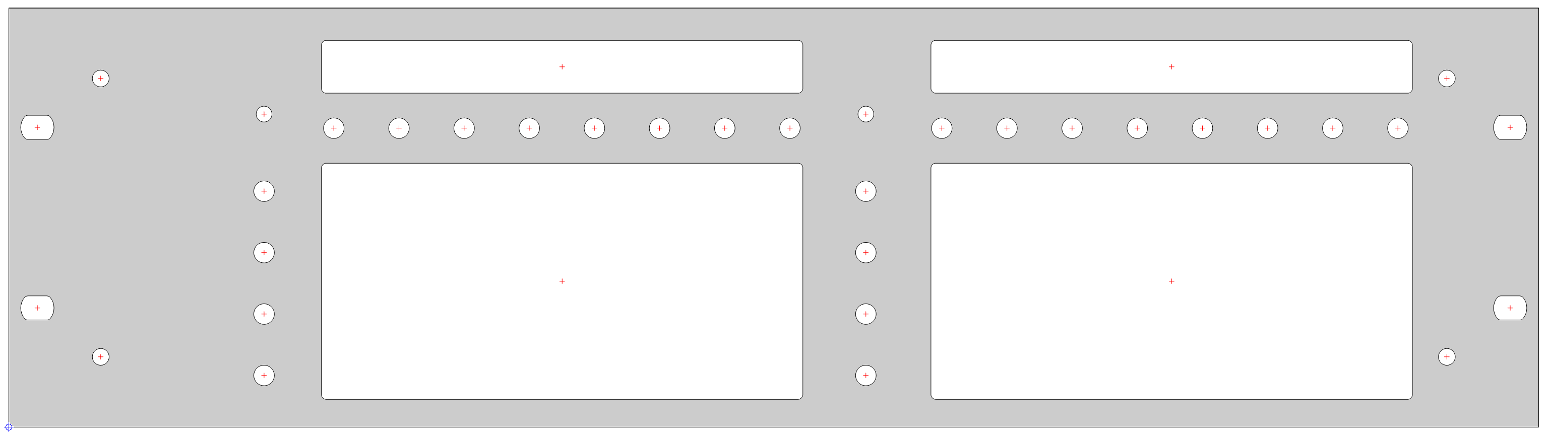
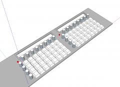
I don't have good chops at 3D CAD, so you'll have to read my explanation :) The main take-home is that the mounting plate is not the front panel! Let's consider a U-shaped case. The top layer is ~3mm aluminium or maybe thinner steel. Next down is the "plate," which has lots of square-ish cutouts. It also carries the encoders and other bits you'll see on the panel. Below this is another PCB where the switches mount, also the BLM and shift registers. There's two lots of 8*4 per build. Below those are whatever PCBs are needed to complete the unit: Core, I2C, maybe AOUT, though I expect a line driver can be added. To the north side of the PCB assemblies sit the LCD/OLEDs and under them newly designed MIDI IO ports. They'll have 8 DINs on each and can be wired as 4 I/4 O or 8 O. I have some ideas to use the space on the left to get the SD/USB out.
-
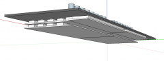
Thanks, it's not 100% accurate but gives a general idea. Now imagine if the north and south edges were bent 90 degrees and formed a U-shape. This adds significant strength to the metal and could allow for panel mounting. The switches are indeed already plate-mounted (using the same PCB that holds the encoders and aux switches). Still, the plate/PCB needs something to fix to! My experience with the BLM is that you need mounting points at least every 75mm or so. The smaller PCB in the current work will help, but it needs consideration. I think I'd be okay with soldering an STM32F4, but you lose the valuable ST-LINK part, so need an FTDI programmer or similar. These would put the project out of reach for many people. Let's see how the jigsaw puzzle pans out. Heh, I think you can use the Discovery Board as a programmer :) More edits: Discovery has an okay power regulator and an ESD snubber for USB OTG, and the whole thing is very affordable. If at all possible I'll try to keep using it.
-
I think it was always intended to provide a case for the SEQ -- absolutely one's required if you're playing anywhere other than your attic (hint: @Hawkeye)! It's something that's always puzzled me, as the case is important to every project, but here was almost an afterthought. There've been enough disasters with money going missing that some folks are understandably a bit wary. I'm in contact with Adrian now and again; he's a nice guy with lots of skills and contacts. Another option is Protocase, like I did with the BLM16*16+X. That one was complicated though as it required studs, milling, threading and precision bending. Great quality and accuracy though. I get what you're saying about reusing the existing parts. I will try to maintain the sizes, but we've gone and squashed a whole extra row of buttons in, and they're quite a bit larger than the TL series. In the end, this is a new project and if things have to change, they will. Just thinking about the idea of metal reinforcement, the panel will be mostly holes and cutouts, so it won't be very strong. (~$70 for one-off). I'm not discouraging anybody, so please keep up the opinions. Better still are solutions to things like mechanical strengthening, mounting options, part suggestions etc. If people want a cheap SEQ, they should stick with the Wilba version. The switches and keycaps alone will likely cost more than the "parts kit" for the former. But I've tested the Matias switches and they light up quite nicely. I'll to look at methods of reverse-mounting LEDs of decent brightness.

-
Maybe something like that, yes :). Some sort of interior panel or mounting rails would also give valuable room to mount things like the Core/AOUT/line driver etc.
-
If you read back, there is no front panel between the keycaps. This is fixed by the 19mm spacing for switches and keeping a 3U height. It's quite commonly done on mech keyboards and the P3 shown above. But it means the boards can't hang off the front panel, at least not where the switches are. It could be done another way, e.g. angled rails or chunky acrylic. But at some point you need to make up that angle as screws can't go around corners. Maybe it makes sense to go for 4U for extra breathing space.
-
A sloping case would need something like these: https://www.ettinger.de/en/product/05.23.401 As it is, the internal arrangements will make even 3U quite difficult. It'll be very hard to make a thin case, mostly due to the F4 Core dimensions.
-
Try http://thebeast.co.uk Not sure if he stocks the case, but will likely do the front and rear panels. Heidenreich in Germany do the cases you see. There was a small order done earlier in the year. FWIW it's not an "alloy" case, but maybe "alu" or "anodised"
-
I suppose +5V.
-
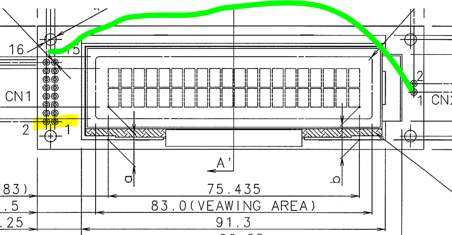
It's still hard to tell from your photos, but it's possible the unlabelled pins on the Base PCB female header are in fact connected to pins 15 and 16. This isn't shown on the current board layout on the wiki, so check with your meter/your eyes to see any PCB traces. In this case, the header assembly should work with no fly wiring. And I bet that's the case otherwise we'd have more troubleshooting threads :).
-

-
Alright, Presuming you have something like this: http://www.kyocera-display.com/SiteImages/PartList/SPEC/C-51505NFQJ-LW-ALN_Eng.pdf Notice the backlight pins are on the opposite side to "normal" LCDs. Check the base PCB layout. You need to reroute the backlight pins to the base header.
-
Wait a sec... The LCD header has 2*8 pins, but they don't line up with the PCB header? Better pictures needed! Don't turn on the power until everything is correctly aligned.
-
Ah okay, looks too thick for an OLED anyhow. You need to connect the backlight on the right side of the board, i.e. the opposite edge from the header pins. Check the polarity!
-
Are you using an OLED display? These don't use the backlight pins.
-
No real quote as of yet from SP. As far as the case goes, I'm doing my best to constrain everything to the same dimensions as Wilba. But it will likely need to be mounted straight on though, as the boards rely on being fixed to the bottom via standoffs. For a sloping case it'd need angled brackets or thick acrylic. I'm aiming for something thin and flat, maybe a two-piece 3mm alu case where the front is bent around to create a side. Wooden end cheeks for sloping desktop use? With keycaps, the main driver will be cost (as we are a bunch of cheap-asses :P ). I asked if SP would paint translucent caps, even 4 sides with one layer removed by us. They said it would be expensive, but available as an option. Maybe a spray can and remove one layer like the video above? Something like this: is perfect (if only relegendable) but sadly not doable by them. AFAIK laser etching is commonly done, but would add to the expense. I'm still keen for a set of blanks with labels printed at home as needed. My switches came, I think I prefer the heavier action e.g. Cherry black over red. The Matias switches are fine but are completely flush on the bottom. They'll need some sort of shine through as @ilmenator suggested.
-

DINX4, DOUTX4 current PCB layout versions needed
latigid on replied to tago's topic in Parts Questions
As tago is after something specialised, namely combining DIN, DOUT and DIOMATRIX (apart from a nicer pinout, I still don't understand why a DIOMATRIX is required) on one PCB, the onus is on him to get the boards fabbed himself (as already mentioned). There are value-added considerations that go beyond a cheap price from China: learning how to use the software properly learning the process of ordering, although it's not too difficult spending many hours/days/weeks on each design making fatal errors on the PCB meaning you have to pay for another run quality considerations, though the standard has increased significantly in recent years arguably you're in a better position by dealing with the company directly if such issues arise also it's less important for small quantities only bought for yourself perhaps buying software, though there are libre programs like KiCAD The upsides are saving some money and you might say learning a new skill (the essence of DIY). The decision to open source the gerber or board files for MBHP would be at the discretion of TK. and/or SmashTV. For the latter, this would undermine his prospects as the de facto provider. If you value his service, especially for other PCBs like the Core etc., consider the situation where he can't continue due to lack of demand across the whole shop. @phat: DOUTX4 is the default way of outputting clocks gates and triggers, so quite relevant for SEQ and MBCV users. -
DINX4, DOUTX4 current PCB layout versions needed
latigid on replied to tago's topic in Parts Questions
Good point, why do the work yourself when others can do it for you, right? It's much easier than learning -
DINX4, DOUTX4 current PCB layout versions needed
latigid on replied to tago's topic in Parts Questions
- the latest DIN/DOUT layouts are not available - I have a board 100*100mm with 6 DINX4 and 4 DOUTX4 on it, some SMT, PM if you want one. - why do you want DIOMATRIX as well as DIN as well as DOUT? -
You should reflash the bootloader by using the ST LINK side of the Discovery Board, then proceed with the application update.