latigid on
-
Posts
2,524 -
Joined
-
Last visited
-
Days Won
149
Content Type
Profiles
Forums
Blogs
Gallery
Everything posted by latigid on
-

Design concept - control surface for VST plugins
latigid on replied to ChinMuzik's topic in Design Concepts
From me :) (custom order of 1000 parts was the minimum to test). -
Design concept - control surface for VST plugins
latigid on replied to ChinMuzik's topic in Design Concepts
Here are the buttons and encoders and the 'ELO board: Sorry for the long-winded explanations. The shine through effect will be much better with clear Waldorf knobs, but I don't have any on hand at the moment. Most of the discrete SMT is for touch sensors (here they are single metal plates), so if you just want the displays + illuminated encoders, the assembly is very straightforward -- shift register chain and some 2*5 headers. @Hawkeye and I are slowly getting the "standard" Programma together, but of course these are good to go for other usecases. Best, Andy -
Design concept - control surface for VST plugins
latigid on replied to ChinMuzik's topic in Design Concepts
While not LED rings, I have some 4*4 encoder boards that use WS2812 LEDs. The simplest MIOS implementation fixes the colour (as RGB or hsv (better)) and uses the level/brightness to indicate the CC value from 0-127. I have two types available; a simple one with just encoders, and a more complex one that uses the 45 degree displays (as part of MBProgramma v2). For buttons, there's a 4*4 matrix using the same programmable LEDs and Sparkfun button pads. Feel free to shoot a PM if you're interested in getting some or you want more info. Best Andy -
@Altitude
-
STM32F4 not recognized by computer
latigid on replied to modius13's topic in Testing/Troubleshooting
CN1 is the miniUSB and is used to flash the bootloader via ST-LINK. It also supplies power to the target. CN5 is the microUSB for uploading MIOS apps. Its "Vbus" is not connected to the +5V required to supply the MCU, so you need a jumper cable or a Core PCB. The issue with the older firmware is an absence of a USB connection in CN1 would hold the main MCU in reset. This was rectified in the later firmware update for ST-LINK v2. -
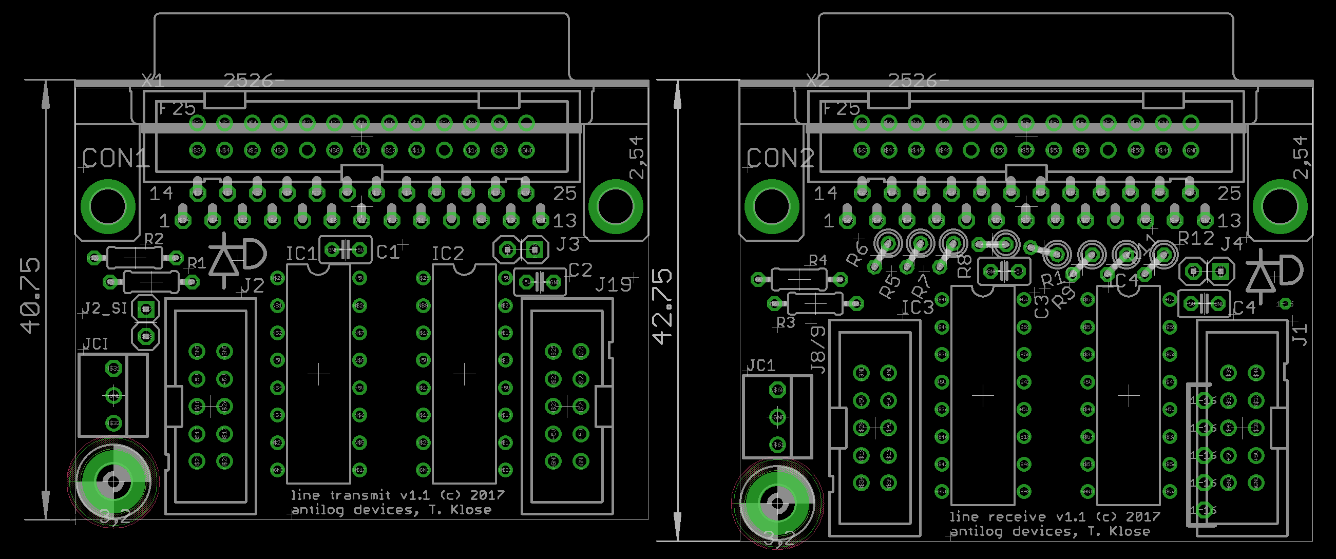
I decided to re-spin the boards: a bit more compact; the idea is to use the panel mount screws for fixing, but there was room for one standoff. If needed, the holes (~3.3mm) in the connector can be utilised instead of soldering down the metal tabs layout improved -- single layer with power/plane on the other side. No vias for the signal lines. +5V is connected through a jumper on both ends, so one could add a power supply if required or disconnect if the cable has too much voltage drop. JAOUT is there, but it would be better IMO to use either a special ribbon cable on the 2*5 or just ensure the AOUT boards have a 1:1 compatible IDC. Alternative connection on a 26-way IDC header. This might be useful if the DB-25 is too chunky or needs a free-hanging connector like this.
-
I route up my boards using separate traces for RC1 and RC2, and I split SC into SC_DOUT and SC_DIN if it's practical. Hopefully it works to tie RC1 and RC2 together where it's needed. IMO it's the "least critical" signal of the SRIO chain as it just tells the shift register when to transfer the 8 bits from storage to the outputs in the case of DOUT, or when to scan the inputs for DIN.
-
If you look at the old PIC8 Core, there was only a single RC line. Now they are separated (different MCU pins and also buffered), but RC1 and RC2 send latch pulses at the same time. I.e. for the moment (and foreseeable future) there's no practical difference between them. This is not the case for other SPI ports, like J19 or J16, where the RCs are "chip selects" for separate peripherals. When Wilba did his SEQ PCB, he simply bussed the two RCs together. My guess is running data busses in parallel is more important when you have chains of DIN/DOUT separated over multiple PCBs, rather than BLMs etc. on a single PCB. Still, the best practice is apparently to split both RC and SC (!) and run whole chains of DIN/DOUT. The SC on the output header is best sourced from the longer chain (either DIN or DOUT): More to the point of your build, RC1 should be routed with the DOUT side, and RC2 with the DIN side. You've done it the other way around. I don't have any DIOMATRIX modules, but from the schem TK. is not following his own guidelines . Because RC2 isn't connected on DIOMATRIX, and your PCBs correctly spilt them, then the result is no connection for the RC2 line on your PCB. I think you can solve this by bridging RC1 -> RC2 on one of the headers e.g. on the output of DIOMATRIX or the input of your board.
-
Is the issue still with the line driver/receiver? Can you get the AOUT to work when using _NG with data passing through the driver/receiver? Often my AOUT_NG needs a reset; it can be that the PSU doesn't stabilise fast enough to receive an init command correctly. This is easiest done by changing the AOUT type back and forth in the CV setup menu (e.g. AOUT_NG -> _LC -> _NG).
-
How to do illuminated encoders (pots) if you're Waldorf: Quite classy, and uses an interesting lens to shine the light upwards. They've even got the bipolar red/green going.
-
This is easy to test, just increase the number of shift registers defined in the NGC (max 32 I think), even if you have fewer in your chain. Now connect some hardware and see if you notice the latency. If you do, decrease the number of SRs until you're happy. Yes. Instead of an 8*8 matrix, define two different ones, or however many you require based on the panel layout. You don't have to fill every position. Draw your panel, divide the thing into sections. Perfboard/stripboard is useful if you have regular 0.1" spacing, also consider the different heights of components and group those of a similar/adjustable height (e.g. LEDs are versatile). I suggest that you go for the direct wiring route. It's a much more linear way of solving the problem, and you're not constrained by fixed geometries. It's easy to address each element and to fix mistakes.
-
Hi Johan, Thanks! As part of the design process the jogwheel is now just a normal encoder (with a push switch). The rationale for leaving the jog/shuttle off: availability isn't great, though could come directly from ALPS size is pretty massive additional software handling is required to scan the absolute position encoder and the spring-loaded sides as this would likely fall to TK., it's extra coding effort that he wouldn't find useful himself, he's a really busy guy! currently there aren't any applicable parameters to match functions on the SEQ I suggested a progressively accelerated increment/decrement, but there wasn't much buzz around the idea Hopefully the normal DK-38 with a push button, along with acceleratable GP encoders is okay (c.f. Machinedrum/elektron stuff). If someone wants to make a PCB for the jog/shuttle and code in the extras, then it's totally doable with modular PCBs!
-
This is awesome! I love the fit-for-purpose design, and the self-routed PCBs are really hardcore. Do we get to see/hear it in action?
-
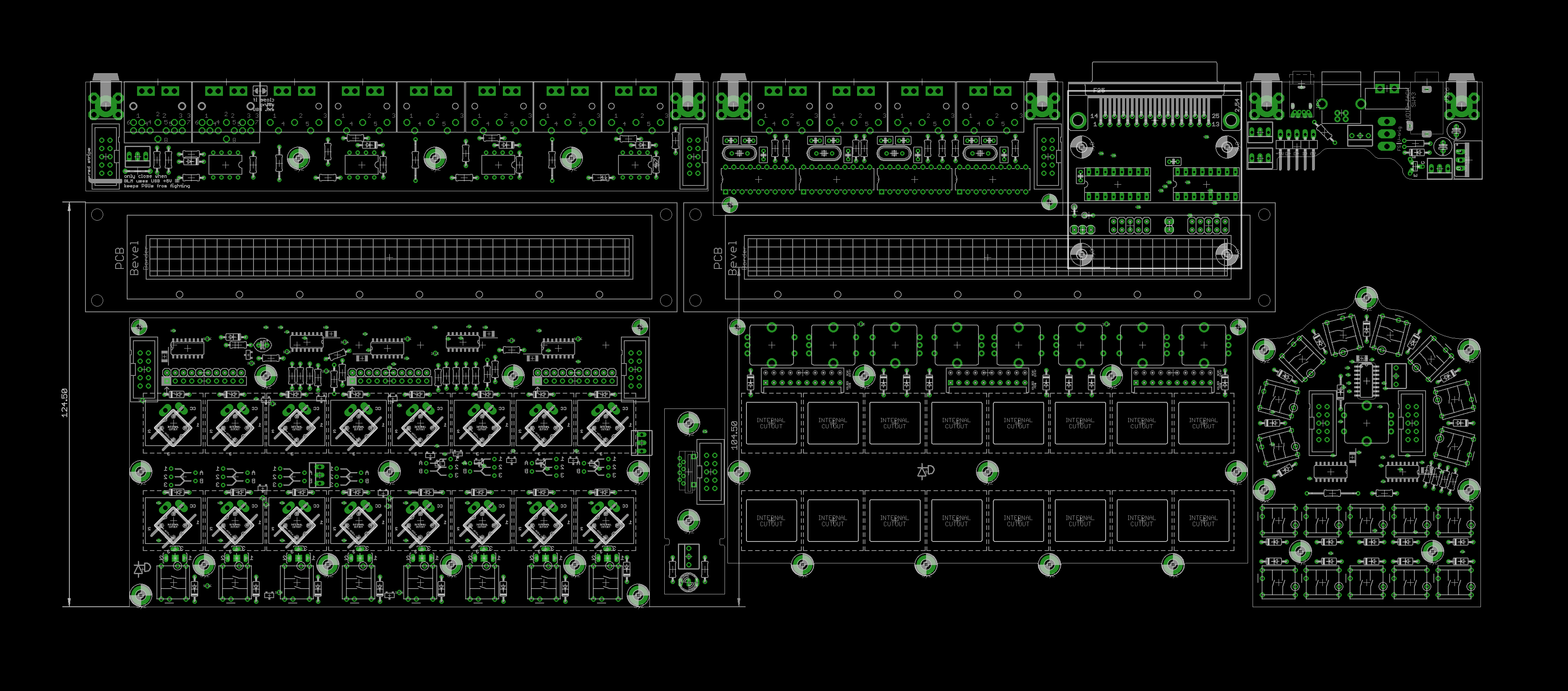
Getting there :-) The modular PCBs are basically done; the top row would be underneath the OLEDs. I was looking at a through hole microSD card on the front, but I'm changing the Core so it will move to the back and turn into the common 3M full sized one. Have to figure out a different solution for the beat LED, which TK. insisted on :-). It might be that the Line Driver can be squashed a bit, but there should be plenty of room for everything, even AOUT/DOUT boards with a breakout on DB-25 (or 3.5mm/1/4" sockets) instead if you wanted. Because the PCBs are modular, you could move the jogwheel into the centre. TK. would say that this disconnects the displays, especially when there's information that flows onto the second OLED. But if you prefer a bit more symmetry then why not? :-) For sure, I'm a DAW-less guy, so this is gonna be the heart of my setup too. Best, Andy
-
HOLY NOTIFICATIONS BATMAN!!!
-
Possible new case option, without needing Heidenreich group buys
latigid on replied to julianf's topic in MIDIbox SEQ
I think the cases look fantastic and it's a good "full solution" rather than the half measures of 19" or desktop panels as has been the case for almost 10 years. They should be a lot sturdier than Heidenreich's. As mentioned elsewhere, the back panel is outdated. I'm currently working on a PCB set that could help for modern implementations, even if people wanted to use the Wilba version over the V4+. When this is ready I'd be happy to share the dimensions in case people want to go this route. As far as "seeing the light of day" I think the risk is more on people like Julian and me, as the activity levels of the MIDIbox community seems to dwindle over time. Of course, maybe there are a lot of "silent" members or it just requires projects to come out of the shadows first. That said, I'm designing something that I would like to use, which is motivation enough! -
When measuring mA, never adjust the dial (e.g. voltage, resistance etc.) with the leads plugged into the mA measurement points. It's a low impedance measurement and you'll blow the fuse if connected across a voltage source. But if the LED still lit up, then the fuse was okay. Maybe you were set to Amps rather than milliAmps? If the PWM speed is fast enough, you should get an average of the current draw. Some meters also have a max/averaging function.
-
If you change your mind it's not too hard to get to know it. Just say if you want a few tips How were your issues resolved by the way? Something simple like the transistors round the wrong way or something? Best Andy
-
I haven't tried this with direct DOUT pins. I know for the WS2812-type LEDs "dimmed=1" will allow a CC to control the dimming level as defined in the LED event. With a resistor, you're burning current*voltage as heat, so yes, switching the LED via PWM should be more efficient. Measure it yourself: set the multimeter to mA and connect it in series after the resistor. You'll need a higher value resistor to match the given dimmed value. Something else to keep in mind is you don't want a panel full of flashlights. The more LEDs on your panel, the lower brightness they should be (depending on how they're spread apart). Check also if your parts have a standard 0.1"/2.54mm pin spacing. If you're inexperienced with PCB design, it will probably take the same amount of time (+mistakes) as going the wiring method. That said, it's a good chance to practice. Consider splitting the panel into subsections, that brings the down cost and shipping is easier. If others find the layouts useful you can sell the extras you don't need.
-
Try dimmed and see how it works for you. Dimming doesn't work properly in a matrix.
-
Matrix or direct drive?
-
Sequencer only boots when connected to computer, not from powered USB hub
latigid on replied to u-link's topic in MIDIbox SEQ
Have you upgraded the ST LINK side to the latest version? -
The way around this is to arrange LEDs of a single colour for each column. It's also important to do this when the Vf values are different, otherwise the current takes the easiest path through the wrong LED.
-
Just try with the bridges, it should be okay with single anode columns 4*4 = 16 :) For this, please read the NGC section:
-
That's right Peter, encoders should be directly connected to 2* DIN pins. With button/LED matrices it can work and does save lots of pins and power, but the additional wiring might be suboptimal. For instance, anything other than a clean, square array will mean rows will be split, but the columns still need to be wired together. Of course, a way around this is to create multiple matrices based on smaller sections, even if not all positions are filled. Best, Andy