

latigid on
-
Posts
2,524 -
Joined
-
Last visited
-
Days Won
149
Content Type
Profiles
Forums
Blogs
Gallery
Everything posted by latigid on
-
Is the range constrained to 255? NRPN works fine for me, at least internally controlling WS2812 hue.
-

"I wish I had a tact with a longer actuator" solution
latigid on replied to Altitude's topic in Tips & Tricks
@Altitude How do you find the feel of these switches? I've heard they're a bit weird, but I have an idea to use them in an alternative SEQ panel. Note that you can buy long, round caps: http://www.conrad.com/ce/en/product/705191/Switch-cap-Transparent-MEC-1S11-190-1-pcs?ref=searchDetail -
Hmm, well that's what @Hawkeye's LoopA is supposed to do, but then there's already the MidiREX https://midisizer.com/midirex/
-
Looks like an awesome custom controller -- well done!
-
After a lot of thought and private discussion with TK., it will be difficult to realise a new SEQ front panel in the given form. The initial concept started very simple and has morphed into something much bigger. The main problem is the new hardware options will significantly change the handling and software. All new ideas sound great, but someone has to code them, and support bug fixes/new feature requests. I am unable to do so, and TK. has indicated he won't have time. So we have a choice: either fork the current software with new options (i.e. SEQ v5), or work within the constraints with some hardware improvements. Assuming nobody wants to step up to take on the coding, a "take one step back" approach could have a 16*3 Matias matrix, with "duo" LEDs for the GP buttons, single colour otherwise, and jog wheel + group/track/layer buttons (+ other suggestions?). 16*3 keeps with the current, adding 4 buttons which are relegendable anyway. So you can give the F1/2/3 buttons dedicated labels too. The keyswitches are nicer, and the panel is simpler. I would need to check, but it's likely the front PCB would be amenable to panel mounting = much simpler case/mechanical design. I'm sorry to those expecting a 16*4 RGBLM for Christmas...
-
Trigger layer has a GP button, mute has a dedicated button. Do they need "extra" ones?
-
Well, we could consider an encoder that scans through and illuminates the 4th row ;-) 808 colours for tracks? Good point. these buttons are essentially the four track groups, no? If tracks were handled on an encoder, then in BLM mode an encoder could scroll through the groups, even using lower resolution if too waggly. Agreed, I'm most sold leaving it on the right. Others may prefer an ordinary three pin encoder. The jog/shuttle takes 6 DINs ( @ilmenator are they detented?) but the scrolling + acceleration could be very nice! I was thinking more buttons above, but I can model some different layouts and ask for opinions. You may want to rest your palm underneath the wheel, or at least not hit anything while jogging. Of course :). The actual rear panel would be very simple: 16 DINs, USB Type A (OTG/host) or Type B via a panel mounted adaptor, SD or micro SD and probably a DB-25 for AOUT/DOUT or line driver. I think that's all that's needed? So -- the modular button and "jog/shuttle" boards can be rearranged as needed. The keys are "relegendable," so you're free to have any paper or professionally printed labels as desired. The difference will be these "extra" buttons that should be defined and the handling considered. With 3D models it's easy to come up with the concepts before anything's ordered. Can we think about modes a bit more? At the moment, GP buttons are used to trigger steps on the selected layer of a track. Will this be retained, or are triggers only actioned in BLM mode? If the latter, then this allows the menus to be accessed without pressing MENU first. This idea has some crossover with BLM 16*16+X: view 4 trigger layers of a single track at once, with the last button press choosing the displayed layer. So a trigger performance matrix. So, there's three ideas for modes: menu, BLM and TPM.
-
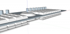
Ah, here's a current shot of case designs, with a 15 degree slope (I believe the Heidenreich case is 12): The strange square/cylinder things are me playing with ideas of how to secure a sloping surface to the bottom of the case. Another:

-
Good feedback -- thanks! There is still space to the left of each 8*4 section -- my thought was to include pads for three (or maybe four) encoders/buttons, and make the PCBs roughly the same dimensions as LCDs/OLEDs. I would recommend only the left-most encoders be installed, in order not to have height conflicts in the middle. Then, as the original idea started, tracks, parameter layers and trigger layers would be accessed via encoders. Wouldn't the handling be better than a multi-mode 4th row? Plus, it frees the 4th row buttons for currently unused or future functions. The "track encoder" would shift the "track group" in BLM mode -- I believe that's how it works for the current 16*4 BLM. Buttons, or even a "data encoder" if the jog/shuttle isn't included, could then be put in the middle, or on the outside. In fact, the "jog/shuttle carrier" could be placed where it suits -- in the middle, on the side, or left out. But it was certainly my idea to include more buttons on this PCB. :) I will try to make the HW as flexible as possible, but it's very important to hear implementation ideas. One thing I like about the current setup is it constrains track selection to one part of the interface. Using the GP buttons or 4th row is a nice implementation and very logical with 16 parameters, but makes one search across the whole interface for the correct track. That's not a criticism, but only an observation. It might be quite different when the HW is set up in another way.
-
DINX4, DOUTX4 current PCB layout versions needed
latigid on replied to tago's topic in Parts Questions
Yes. DIN DIN DIN DIN || DOUT DOUT DOUT DOUT = split vs DIN DOUT DIN DOUT DIN DOUT DIN DOUT = series None at the moment, future compatibility. -
Can support for jog shuttles be implemented? A very common component has the following encoding: The central "shuttle" is an absolute type with 10 degree resolution (36 pulse per revolution rather than the normal 24), while the outer "jog" is normal Gray code. I propose the jog be assigned to up/down buttons combined with increasing amounts of FAST, e.g. something like:


-
DINX4, DOUTX4 current PCB layout versions needed
latigid on replied to tago's topic in Parts Questions
To be sure you should generate the gerbers and check them before rather than sending the .brd. For when you chain DIN and DOUT serially rather than with a split IDC. RC was shared for MIOS8 but is split for MIOS32. To maintain upward compatibility, separate the two. -
Absolute = unique code for each position, relative/incremental = direction info only (and commonly used in MIDIbox). I found a fleamarket post of yours that you had a bunch of jog shuttles, are any left? Both the knob and mechanical parts are on the inventory at ALBS.de Internal case height = 45mm, not too accurate on the Core positioning (needs a carrier).

-
I'm still confused about what's jog and what's shuttle :) I found a more detailed datasheet So the "shuttle" is an absolute position encoder (10 degree resolution?), while the "jog" is apparently a 10 ppr relative encoder. I think the latter function is limited in its rotation with a spring return, not sure though.
-
No. The displays are hard up and that's the minimum spacing (check on Wilba's). No, at least not from me. Rubber pads are not aligned properly and are too small to put an RGB LED underneath, let alone the whole top layer is exposed copper pads. Maybe with a 4-layer board, but then you're back to costs going up. 200 Matias switches are 40 GBP or so, 16 adafruit pads are 5 USD. So about the same price. It's non-trivial to get pads and encoders on one board due to vertical spacing (milling needed). No real space for legends on the front panel, unless you have (special silicone glue) stickers as TK suggested. Anyway, thanks for your input.
-
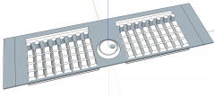
Maybe we do need a jog/shuttle after all? In the middle or to one side? (Could be made lefty too.) On one hand I like the symmetry, on the other the x edges of the display windows are ~60mm apart vs 30mm (closest they can be). The clear benefit is the jog carrier PCB would be about the same size as a Core and mount above it = fewer headaches trying to dance around standoffs on the switchboards. How then to assign tracks (/groups) and layers? A few more encoders? Or buttons to assign track/layer scrolling on the jogwheel? Or, make use of the 16 buttons along the bottom row. I think it makes best sense to have switches separate from the BLM though so you can go through tracks on the fly without changing modes. How to handle the shuttle? If it's no good to use the Core ADC, a separate chip would be easy to do. The resolution doesn't even need to be very high.
-

From the album: Mech SEQ
© 2016 latigid on
-
From the album: Mech SEQ
© 2016 latigid on
-
From the album: Mech SEQ
© 2016 latigid on
-
DINX4, DOUTX4 current PCB layout versions needed
latigid on replied to tago's topic in Parts Questions
General tips: clearance looks quite small; increase the distance between traces, pads and holes avoid running traces between pads if possible (e.g. SI) route ground/0V as a plane rather than a thin trace route power as a thicker trace avoid layer changes if possible (minimise vias, e.g. D4) minimise traces crossing; normally I run +5V around the outside of the board. identify the orientation of components better using silkscreen (ICs, RNs) -
http://www.albs.de/ecom/images/869001.pdf jog shuttle knob for reference diameter = 55mm! JSK5542-88 https://www.aliexpress.com/store/product/ALPS-jog-shuttle-type-switch-SRGPHJ/514132_32495198210.html $14 each @ali
-
Comparison with DCS (best guess at the shape). Panel was removed.


-
A few extra thoughts perhaps. I didn't cut out the panel where the switches go, but it would need to be fully removed around them. The combined PCB y dimension is perilously close to 3U (the panel given is spec'd to ca. 483 * 132 mm). I think it should still fit, but maybe in a steel case with thinner metal. 4 encoders on the vertical seems too cramped.
-
I saw those at Mouser, about $5 each and a smaller size. The height is difficult to work with, unless there's a carrier PCB. Nice! Meanwhile the official ALPS combo jog/shuttles look to be unobtainium, unless you have a reliable source to salvage? The huge size and difficultly finding compatible panel hardware makes it unlikely, although it would be super cool to add. So I had a go at modelling the current idea. The alignment isn't perfect but you get the gist I hope.
-
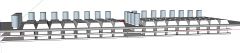
From the album: Mech SEQ
© 2016 latigid on


