latigid on
-
Posts
2,524 -
Joined
-
Last visited
-
Days Won
149
Content Type
Profiles
Forums
Blogs
Gallery
Everything posted by latigid on
-
I get a similar issue; larger file downloads (and "Edit Text" commands) always time out using an STM32F4 Core. This was on Win10, so I tried on an older Win7 machine. Interestingly I could replicate the problem there, but after a bit of fiddling around with downloading smaller then larger files I was eventually able to Edit Text on everything. Back to the Win10 computer, even this didn't help. An acceptable workaround is to edit text files in your favourite program and simply Upload to the Core/SD card that way.
-
Maybe for real coding, but this is MIOS so everything's a MIDI stream with limited parameters. I did play around with senders and multiple ids/hw_ids, but there's still the problem of one EVENT_RGBLED overwriting the other. Eventually I could get it to work in a script, but it's pretty crude NGR: if ^section == 0 exec_meta RunSection:1 endif #testing purposes, called at the same time as .NGC if ^section == 1 log "Section 1 called" if ENC:3 < 50 set_hsv RGBLED:3 0:100:50 elseif ENC:3 == 50 set_hsv RGBLED:3 60:100:60 else set_hsv RGBLED:3 120:100:50 endif delay_ms 100 exec_meta RunSection:1 exit endif #loops until "runstop" is entered into MIOS terminal :s NGC: ENC n=3 sr=1 pins=5:4 type=detented1 enc_speed_mode=Fast:5 EVENT_ENC id=3 fwd_id=RGBLED:3 fwd_to_lcd=1 type=CC chn= 1 CC= 18 range=0:100 lcd_pos=11:1:1 label="ENC #%3i %5d%B" EVENT_RGBLED id=3 hsv=0:100:50 dimmed=1 range=MAP3 I hope there's a nicer way to implement it.
-
I've been playing around with illuminated encoders and the results are nice (promise a video soon!). For the most part, the NG events work well to change the hsv colour, or brightness using dimmed=1. I'm wondering about bipolar controls though -- e.g. where you might represent CC* values of 0-63 as negative and 64-127 as positive. I find it's okay to use range=MAP* as a hack to assign red to "negative" and green to "positive" values, and also to use a dimming function e.g.: #hue map (red 0-49, yellow 50, green 51-100) MAP1 0 0 0 0 0 0 0 0 0 0 0 0 0 0 0 0 0 0 0 0 0 0 0 0 0 0 0 0 0 0 0 0 0 0 0 0 0 0 \ 0 0 0 0 0 0 0 0 0 0 0 0 60 120 120 120 120 120 120 120 120 120 120 120 120 120 \ 120 120 120 120 120 120 120 120 120 120 120 120 120 120 120 120 120 120 120 120 \ 120 120 120 120 120 120 120 120 120 120 120 120 120 120 120 120 120 #value (i.e. brightness) map (value 100-0-100) MAP2 100 98 96 94 92 90 88 86 84 82 80 78 76 74 72 70 68 66 64 62 60 58 56 54 52 \ 50 48 46 44 42 40 38 36 34 32 30 28 26 24 22 20 18 16 14 12 10 8 6 4 2 0 2 4 6 8 \ 10 12 14 16 18 20 22 24 26 28 30 32 34 36 38 40 42 44 46 48 50 52 54 56 58 60 62 \ 64 66 68 70 72 74 76 78 80 82 84 86 88 90 92 94 96 98 100 but it would be nice to combine the two. Thus you might have the LED off in the centre position, and fade up to full red or green depending on the direction. I can also think of other usecases e.g. a unipolar level control increasing in brightness from zero to green to yellow to red. All of my efforts so far have failed, including trying to put conditional statements in the .NGC, running simple SET_HSV commands in .NGR, various arrangements of EVENTs etc. I assume (as well as being naive) that the RGBLED events are conflicting, and only the most recent one takes priority. So, any ideas for controlling both the "h" and "v" parts of EVENT_RGBLED separately?
-
http://www.ucapps.de/mios_download.html If the setup's too confusing you might consider a fresh install using MIOS Studio and the MIDI ports. Sometimes TK. will configure different hex files, otherwise you need to edit the .asm and recompile.
-
http://midiboxshop.bigcartel.com/product/core-stm32f4-board-kit No need to breadboard. IMO this is almost the simplest MBHP to build and there's very little to go wrong. Maybe see how you go with the 8-bit and if it's too hard consider a Core upgrade as a solution. Good luck!
-
It could be a connection problem or it might just need configuration. Have a look here for the info: http://www.ucapps.de/midibox16e.html I don't know how familiar you are with electronics/MIDIbox etc., but what you have is a grid of panel mounted encoders and switches, which are scanned by shift register "modules" stuffed with 74HC165 chips. These form the SRIO chain. The Core is the brain of the operation, and newer generations are not only backwards compatible and easier to configure, but are faster and offer more hardware options (increased MIDI IO, USB, OSC/Ethernet, SD storage, etc.). It's a whole new board though: http://www.ucapps.de/mbhp_core_stm32f4.html
-
Are any Banksticks installed? http://www.ucapps.de/mbhp_bankstick.html Judging from the wiring it's probably an MB64E. You could upgrade to a 32-bit Core, then the configuration and patch storage is easily done with SD cards.
-

Weird issue with MIOS Studio under Windows 10
latigid on replied to BEBDigitalAudio's topic in MIDIbox Tools & MIOS Studio
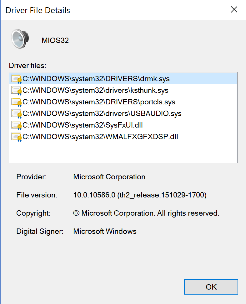
Mine's listed as MIOS32 with the following drivers:
-
http://www.generalguitargadgets.com/how-to-build-it/technical-help/schematics/

-
Weird issue with MIOS Studio under Windows 10
latigid on replied to BEBDigitalAudio's topic in MIDIbox Tools & MIOS Studio
I can work my way through French okay, feel free to post (could be useful to others also). I edited my post above with app_skeleton built and it works fine, maybe try that on your Win10? That might narrow it down. -
Weird issue with MIOS Studio under Windows 10
latigid on replied to BEBDigitalAudio's topic in MIDIbox Tools & MIOS Studio
Okay, I just built app_skeleton and I get recognition of the USB MIDI device afterwards. You can try with my version if you like (attached). project.hex -
Weird issue with MIOS Studio under Windows 10
latigid on replied to BEBDigitalAudio's topic in MIDIbox Tools & MIOS Studio
If you like I can try to compile here on my environment -- can you list the dependencies? (SVN?) -
Weird issue with MIOS Studio under Windows 10
latigid on replied to BEBDigitalAudio's topic in MIDIbox Tools & MIOS Studio
Hi, I get the same behaviour with no valid MIDI devices installed after firmware update via MIOS Studio. I have no problem with any of the other MIDIbox stuff (NG, CV, SEQ, diagnostics etc.). Hope that you can locate the issue! Best, Andy -
I've never built a SID module (just the MB-6582), but the MBHP module only takes one chip, so yes you need an additional one if you want a stereo pair controlled by one Core8. Just write to Mike and see how he can help with PCBs. For your own solution, I'd say that would be possible and you would get some interest. You just have to follow the schematics on uCapps and combine the modules rather than interconnecting them with cables. Before selling PCBs, you must prove the concept first. But with a prototyping batch (e.g. 10 boards) it's generally okay to sell the extras that you don't need.
-
"MIDIbox SID 8580 / 6581 + CS" is the SID kit set on Mike's site that you want. I think he still provides PCBs and PICs, possibly other parts but I don't know. You can also get PCBs and source your own parts. Where you buy from depends on your location. If in the US or nearby try http://midibox-shop.com/ Note you have to build your own control surface linking the DIN (digital inputs = switches and encoders) and DOUT (digital outputs = LEDs). It's more of a classic MIDIbox this way. You can choose how complicated to build based on your skills, time etc. http://www.ucapps.de/midibox_sid_cs.html http://www.ucapps.de/midibox_sid_csB.html http://www.ucapps.de/midibox_sid_csC.html
-
http://www.ucapps.de/midibox_sid_manual_hw.html That shows you everything you need to build your own SID. If you want a more compact solution, it's on you.
-
You can find layouts for SID, PIC8 Core, DIN, DOUT and so on on http://www.ucapps.de/. With these files you're welcome to make your own PCBs for personal use, and they've been there for at least a decade. Maybe you want to clone the MBSID for commercial reasons, maybe you want to just etch your own boards at home. But the easy answer for you is: no one is going to give you design files for sammichSID or a complete project like it. But if you're interested and have skills to make boards, maybe you can come up with a similar project. I'm sure there'll be many people interested :).
-
Weird issue with MIOS Studio under Windows 10
latigid on replied to BEBDigitalAudio's topic in MIDIbox Tools & MIOS Studio
If you like, attach the .hex and I can try it over here. FWIW, did you try updating the ST LINK firmware to LINK007? I know with older firmwares on newer DISCOVERY boards it can have trouble with USB when the mini USB side is disconnected (I've posted that in various threads over the last couple of days). Win10 can also have issues with MIDI drivers. Also note on MIOS32_download: -
Goom STM32F4 USB Problems
latigid on replied to boredofchoosingnames's topic in MIDIbox User Projects
Instead of soldering jumpers etc., try upgrading the "bootloader" firmware to LINK007. This solves the issue of the STM32F407 chip being held in reset when the mini USB isn't plugged in. -
And another update (might be good to merge the threads); if you install the Link007 firmware, the problem disappears with no hardware fixes needed.
-
Problems running app on new STM32F407G-DISC1 pcb
latigid on replied to illogik's topic in Testing/Troubleshooting
In fact, it's easier than this. ST released a new firmware for ST LINK (STSW-LINK007) that removes the requirement for USB host to be present. If your device exhibits problems, try upgrading the firmware (mini USB side). It only deals with the "bootloader" side; it's not necessary to re-flash the F407 chip. -
Okay, just to close the loop, I noticed an error behaviour: So it seems as if the newest DISCO boards aren't exactly the same, but this simple fix of removing two links restores the expected functionality.
-
Nice job! I managed to do it the old fashioned way the other evening, just setting environment variables by hand and invoking "make" from the project directory. But this looks easy enough for anyone to try :). With Eclipse are you able to set different "presets" for distinct build environments? I know you can run into trouble with multiple toolchains etc.
-
Problems running app on new STM32F407G-DISC1 pcb
latigid on replied to illogik's topic in Testing/Troubleshooting
Today I experienced the same behaviour on my board marked MB997D. The fix noted above works perfectly, just remove link SB11 and resistor R68 (100R). Both are on the underside of the Discovery board. LED1 now blinks red (perceived lack of USB host I assume), but it still boots into ST LINK okay (I didn't try flashing the bootloader). Maybe to clarify: I had already gone through the MIOS bootloader process, but afterwards, unless the mini USB (ST LINK side) was connected the computer wouldn't recognise the micro USB, i.e. it wouldn't show up as a MIDI device in MIOS Studio. This confirms the poster's theory that an absence of USB on the ST LINK side holds the board in reset. SB11 and R68 are still present on the MB997C revision and I can't see any other layout or jumper configuration differences, so it must be down to firmware (?) on the STM32F1 side. No problems here using an LCD on J15A. I don't recommend bridging SB10, because that will negate the effect of a power on reset (pin is low while capacitor C11 charges) and also renders the RESET button useless. -
Hi, somehow I missed your post. I'd make the following points about your design: Ground scheme/trace layout isn't the best, the digital stuff has free reign to interfere with the analogue by way of coupling through the top layer plane. Some quite thin traces (10mil), going through capacitors and the like. Power connector is non-standard (suggest a Eurorack 2*5 DIL or polarised Molex SIL). Also note that the "digital power and ground" comes in on J19 (CONN1 on your layout); but I notice jumpers for connecting/disconnecting these. In the meantime I've come up with my own solution: It's a four-channel board and uses two quad op amps for this. But you get range and offset switching plus a fine tune control out of the box. It stacks with an associated control board with 3.5mm jacks that also carries DOUT gates and indicator LEDs. To be honest, I think the switching can be done manually, presumably as you re-patch at the same time anyway. While it could be done with a digital IC (or FET perhaps?) the risk is that you inject digital noise into the sensitive analogue summing node (op amp inverting input). My concept also uses a switch pole to add/remove a resistor from one op amp stage, which varies the gain. This would be expensive (and a bit risky in terms of noise) with an analogue switch IC. Maybe vactrols would work :), but I made do with mini DPDT switches and indicator LEDs. @Altitude also did a fully SMT version with eight channels, all DOUT gates, extra triggers and clocks on the one board. To be honest, I'm not sure how much interest there is in these MAX525 boards. I think the price of the DAC puts people off, even though it has better linearity than TLV5630. If users are keen I'll do a run of them, otherwise I get personalised CV for myself :). Best, Andy