latigid on
-
Posts
2,524 -
Joined
-
Last visited
-
Days Won
149
Content Type
Profiles
Forums
Blogs
Gallery
Everything posted by latigid on
-
Maybe try 3V/3V then, this would load the Vreg a bit, but apparently only to 60mA. Could be noise on your USB 5V buss?
-
How did you set the Core LCD voltage jumper?
-
Exactly, it's a question of whether the effort of testing a new layout and code is worth it to save a few bucks in 16F chips and a bit of board space. I can certainly look into it, but I would likely need a bit of help with the firmware. Well, I checked the assembler -- it's nicely annotated but still a bit beyond me. I.e. I can easily set the baudrate to match the faster CPU but there's lots more going on :). Would you keep the I2C addresses the same but fill separate buffers, or run different ports completely in parallel (presumably the former to maintain compatibility)? If you could suggest a basic direction I can see if it's manageable from my side. @yogi, I was considering the out-only version to keep things simple. SPI would be an interesting solution (fast enough?), if space/cost wasn't an issue you could interface to another dev board -- even STM32 :). Best, Andy
-
Okay, I built the app for STM32F1, I didn't try it on my Core. project.hex
-
Do you have a PIC or LPC/STM32F4 Core? You should test your DOUT module, but the MIDIO128 app isn't compiled for STM32F1. Also, you're using an old rev of DOUTX4, so again check your wiring. It's possible to kill CMOS chips, for instance with reversed power connection, so you can swap in a spare. http://www.ucapps.de/mbhp/mbhp_doutx4_r5.pdf The correct signal to send to DOUTs is SO, located on the top of the header relative to the polarising notch. Understand too that the connector on Wilba's board is mirrored. I just tested my F1 Core with DOUT, it works fine but only if you've initialised with J5_ENABLED 0 Copy a new MBSEQ_HW.V4 file to your SD card (comes with the latest firmware) to be sure.
-
Keeping it in the family, the following are 8-bit PICs with >2 UARTs PIC16F15354 PIC16F15355 PIC18F23K22 PIC18F24J11 okay PIC18F24J50 okay PIC18F24K22 PIC18F25J11 EoL(?) PIC18F25J50 okay PIC18F25K22 okay PIC18F25K80 SOIC PIC18F26J11 okay PIC18F26J13 PIC18F26J50 low availability(?) PIC18F26J53 PIC18F26K22 SOIC PIC18F26K40 PIC18F26K80 SOIC PIC18F27J13 SOIC PIC18F27J53 SOIC PIC18F27K40 Basic specs: PIC16F88 / PIC18F25K22 / PIC18F24J11 / PIC18F24J50 / PIC18F25J11 / PIC18F26J11 / PIC18F26J50 Data RAM Size: 368 B 1.5 kB 3.72 kB 3.72 kB 3.72 kB 3.72 kB 3.72 kB Program Size: 7 kB 32 kB 16 kB 16 kB 32 kB 64 kB 64 kB CPU Frequency: 20 MHz 64 MHz 48 MHz 48 MHz 48 MHz 48 MHz 48 MHz Supply Vmax: 5.5 V 5.5 V 3.6 V 3.6 V 3.6 V 3.6 V 3.6 V Accordingly PIC18F25K22 looks the best as it's 5V and available in good quantities. Heh. Probably needs a PICkit 3 programmer though...
-
Previously: I'm wondering about a new design, likely as a separate board(s) wired to 8 DIN5 sockets. PIC16F88 is still available, and I have the programmer so can flash them. But is this the best way? There are other MCUs with 2/4 UARTs, also dedicated chips for the purpose (fine pitch soldering). Or, is it the simplest way just to dedicate one PIC for every port? Any thoughts or ideas?
-
Sorry for the confusion and crappy orthographic projections. To get a better idea, look for teardowns of various mechanical keyboards. You'll see the intermediate "plate" for mounting cherry switches -- normally piece of sheet metal. In this SEQ build, you'd need two switch/register boards, two plate/encoder boards, two LCD/OLEDs, Core, MIDI IO etc. That's the good thing about the Sunlike OLED :). The bezel is a bit larger, but a similar thickness and they've managed to maintain standard 33.5mm PCB height. It's really an OLED as there's no connection to B+/B- (normally pins 15/16). If you've got a spare 5mm in your case the more common ones will do, though I'd prefer a neutral colour like black/white. Rated for 2,400 VAC @ 908, 200 mA Fun times!
-
Not quite. Here's the current design: At the left and centre you have two sets of multi-functional pads; from these you can select a maximum of 8 DINs. So 4 encoders, 8 switches or combinations of these. You'll have to configure them with jumpers. Newest design: Same deal, you see one half as the switch board, one as the "panel" plus encoders/aux switches. I've reverted to Cherry MX switches as they're more widely available and have more options for caps. Speaking of caps, X-keys (did somebody mention them already?) look okay. Transparent would be needed I suppose. http://xkeys.com/accessories/Keycaps.php Something to note is the boards would need to be stacked before soldering in the switches (I found you can socket MXs too if this is a problem) and screwed in from the outside of the case. You see that I've considered a new carrier board for the Core as well to fit between mounting standoffs. If I can find one I'll also look at vertical PCB mount SD cards to have that accessible on the front, otherwise the carrier PCB goes beyond 100mm and is more expensive. USB would be via a micro to type B or OTG connector. I was hoping one of the PCBs would extend past the displays to hold the MIDI connectors. Seems that's too hard, so I'll make another board with 8 DINs on it. These can be configured as 4 IN/4 OUT or an octal I2C -- the latter probably with yet another board holding PIC16F or something better. Of course fewer DINs are also possible. One set of IO can be subbed for a BLM connector or other peripherals. Here's a rough sketch of the internal heights: You can see a 3mm panel, the switch mounting, ALPS STEC12 (STEC11 off to the left) with Re'an P401 knobs, LCD, OLED (thinner) and a MIDI socket hanging off the bottom. Total height might be about 40mm. I'm a bit uneasy about the distance of cutouts to the panel edge, but there are other strategies like using a U-shaped case where the bend adds some strength. The OLEDs I found normally have an annoying extra 5mm added to the PCB height, which is okay if you're building a Ponoko/Formulor case but not good for fixed rack units. The following displays should fit as they maintain a standard PCB size of 182*33.5mm: Cheapest and crappiest. http://www.buydisplay.com/default/character-display/40x2-character MIDAS do a black on white transflective LCD that looks nicer: http://www.midasdisplays.com/pdf/MC24005A.pdf Even better is this OLED: http://www.lcd-modules.com.tw/page/product/show.aspx?num=183&kind=59&page=1 It doesn't seem to be available anywhere so I've sent an enquiry.


-
6mm tact swtich: DT6: I can use multi-format footprints for a few different switches. The arrangement would offer a choice between encoders and switches in line with the aux encoders (left and centre). At the moment, the LCD is a standard size of 182*33.5mm, although I've come across a few OLEDs that can have a larger mounting PCB. That could be problematic. I think a neutral colour will be best e.g. black on white or vice versa. It'll certainly be a big puzzle to get all the pieces fitting together with proper clearances. Did anyone contact Fentek yet?
-
Good idea to ask the experts! As far as I can make out a "1x spacing" key should fit just fine in the x and y dimensions. Somewhat uncannily the spacing of 19mm used to match the encoders to the display pixels is standard for keyboard layouts(!) Still need to do proper measurements in the z direction though. Note the encoders and display will sit somewhat higher as they're on the "mounting plate." The switches probably need to be ALPS mount to work. Cherry MXs have a smaller but square profile leaving little room for stacked headers etc. A clicky data wheel's a good idea. I can put the footprints in for switched encoders that can be enabled with solder jumpers, maybe optionally joined to the "fast" buss instead. You can fit non-switched in place of course. Another degree of freedom is the encoder shaft -- the shorter the better though (less wobble). Preferences for switches? Easiest is standard 6mm and DT6. A tip for DIY blank keys from a yobbo: FWIW, don't expect megabit colour depth unless we use fancy PWM drivers in place of shift registers.
-
@mongrol I was indeed wondering about a backplane with sparser mounting holes to fit a Core etc. under. Hanging the encoders off the front panel would strengthen the aluminium and provide another anchoring point for PCBs. @u-link Yep, that's what the right-hand PCB in my previous image is doing. The switches "plug" into that and then get soldered onto the other one. The mech switches are fairly tall, so this allows the encoders to rise a bit. Thanks for contacting keycapsdirect! The good thing we've got going is the PCBs are about half the size that they use in smaller mech keyboards. E.g. pok3r has just 6 mounting holes and what looks like 3 little shelf parts on the edges (295*102mm) Low profile alu case here In that sense maybe all of those mounting holes on my design are a bit much. I'll look at building in the MIDI IO, maybe a BLM port, but the Quad IIC will be a bit too much. This means the aux encoder boards would be amalgamated. I think there should be three encoders max per line, and without switches (no menu switching functions with encoders, right?). Instead I can add two extra switch footprints to fill up a DIN, and an RGB LED with dedicated DOUT pins. In this case all of the DIN routing would be on the top board and all of the DOUT on the bottom.
-
For sure, the encoder switches could act as row 4, but it's likely you'll mis-press and enter a menu instead of changing values. For size, it depends on your definition of 3U I would prefer 3U full panel, as I have a mind to rackmount. The whole thing could squeeze into 122mm (left-hand white block is a 3U panel -- slim margins!). For Eurorack fiends, they might try out your idea of a single encoder and overlap the displays in place of 16 GPs, if that's even possible from a UI perspective. (I can envisage that GP buttons would only toggle gates in BLM mode, and enter menus directly otherwise.) The day's research found that the Matias switches could work. This assumes that the DSA family of re-legendable caps come in ALPS mount. Seems the LP caps are just for Cherry ML = no backlight. Matias are cheaper than Cherry but need to click into a "panel" to stabilise them. I figure a PCB will do, and it would have the encoders on to gain a bit of extra height (right-hand PCB). The other has switches, LEDs, the 8*8*8*8*4 matrix and registers stacked underneath. Let's discuss the case build. A tricky point is that there's very little room for mounting holes; in fact the panel would have four big cutouts for the displays and switch arrays, plus ~20-something holes for the GP/data/track encoders and a few LEDs, and not a lot else. I think it would need rear standoffs (viz. Mongbox) and a flat bottom. What are the other components? Core, MIDI IO (white oblong), Quad IIC or two, maybe AOUT/DOUT or line driver. The big question is how many standoffs are needed to prevent flex? With fewer, more things can fit inside a flat case but may cause bending. Desktop users could mount a smashTV Core sideways (mounting holes line up) with some extension to the right-hand side. Another option is to redesign the Core carrier board so it can be panel mounted along the long edge and fix it to the right of the panel. SD card and a few other things could go on the front, USB can use a dinky adaptor cable and at the same time go for more robust Type B or OTG (USB Host) panel sockets. With the switch PCBs extended, DIN sockets might fit, even 16 of them (2* MIDI IO, 2* Quad IIC, BLM. In that case the whole lot could be widened, but that's a story for another day. The PCB cost would go up because at the moment it's a magical Eurocard size. What else needs to be crammed in?

-
Next beer's on you! may be the issue with your bipolar range.
-
Press EXIT and scroll through until you get to CV Configuration:
-
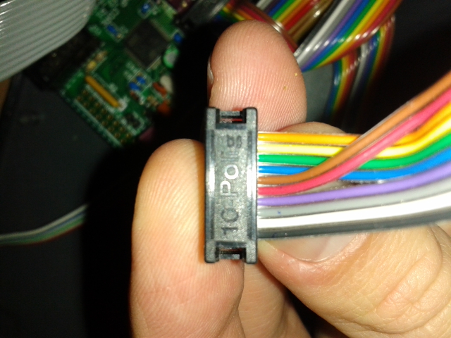
I'm a bit confused by your second sentence -- it doesn't matter what end of the connector the cable exits, as long as you know where pin 1 is. Having the keyed pin header helps to get the orientation correct. For 5V, did you select the correct voltage with the J26 jumper? No jumper = no voltage. Make sure the resistor network is the right way around also.
-
If you were to patch 12V to your gate output by accident, you'd blow up the chip. Best to use a resistor at least, or the other strategies I mentioned.
-
Triggers or gates are available at J5A and J5B on the Core, 8 total. The voltage level is only 3 or 3v3, so you need a level shifter (transistor, op amp comparator or CMOS) if you need 5V or higher gates. Also these aren't current limited, so you have to be careful not to patch to an output on the modular if you use one. If you need more gates or triggers, expand with a DOUT module. Then it makes better sense not to fluff around with J5A/B and level shifting/protection, and one DOUTX4 gives you 32 bits to play with, or I think you can use some pins as LED drivers.
-
Notice the STM32F1 Core in the background -- it works! But the F1 also uses GPIO for gates on SEQ v4, so no DOUT necessary.
-
1:1 pinning on the other end attached to J19 and just use the top row onto the SIL header. (nowadays I would have brown as position 1, black as 10 according to standard resistor codes.) I'll update the wiki.

-
Down the rabbit hole of mechanical keyboards! Apparently clones of Cherry MX are now being made after their patent expired in 2014. I found this: https://zealpc.net/collections/switches/products/zealio Essentially MX clones for $1 each. They also have custom RGB common anode THT LEDs made to fit. They have an open-source keyboard project too, with an old friend active there: https://geekhack.org/index.php?topic=81026.0 Also: https://www.massdrop.com/buy/smd-led-compatible-gateron-switches (needs a login) Matias Quiet linear (uses ALPs mount): https://deskthority.net/wiki/Matias_switch I know there's a lot of love for Cherry MX, but the "ALPs-type" would give crucial vertical space on the PCB. Better still would be re-legendable key caps in a rectangular shape. Anyone know a source? Re: using encoder switching functions for menus -- not recommended. Also with a 16*4 button matrix, there's no free DINs, normally they're bussed to FAST or similar. Re: the extra row -- no new functions as far as I know, but you could consider all sorts of possibilities e.g. direct access to tracks, step view like the 16*16 BLM does, song positions. There's a strong case for the fourth row and making a timeless instrument with high-quality switches.
-
They say a camel was the result of designing a horse by a committee ;). I've had suggestions promoting 3U as a) it's appealing to modular DIY and b) it provides an avenue for premade cases. Some people prefer to have sequencers amongst their other modules, but mine is more tabletop. Some day it will live in a sloping rack with MBCV. A slimmer build doesn't preclude desktop case mounting. Anyway, I duly note your point and welcome further discussion in this ideas thread.
-
The re-legendable caps look great! I think the issue comes down to size though. With a cap of 18.415mm it needs a 19mm grid in each direction. That's fine for the horizontal and matches the encoders, but would add a further ~20mm to the overall height. And even then it's a very solid array of buttons with no room for mounting holes, and lots of through holes to avoid. A 16*3 matrix could work.
-
I tested the current draw for 16* WS2812 (5mm THT package): "rainbow mode" rate 10 (average values) brightness 10: 32mA brightness 20: 77mA brightness 30: 120mA brightness 40: 164mA brightness 50: 204mA hsv 120:100:10: 26mA 120:100:30: 89mA 120:100:50: 147mA (other single colours similar) 120:0:10: 56mA 120:0:20: 147mA 120:0:30: 227mA 120:0:50: 309mA 240:10:50: 345 mA Bright colours could still be done with POV to reduce current, but that's pushing more data and using memory. Meanwhile, I tested the fit of 16*4: It might just squeeze into 110mm, maybe you'd have to file down the LCDs. Are the switch pads okay like this? No need to cut them then, and this would be the most stable arrangement. A variation splitting each into two: Cherry switches could also be nice, the MachineDrum uses something similar with 19mm spacing. Would be really tight though! ~1.50 US each on taobao.


-
The typical method is to use a button-LED matrix (BLM). You scan columns of switches (via diodes) using 74HC165 and drive columns of LED anodes using 74HC595. The cathodes of both are connected in rows to another 595, but normally transistors are added to improve current sinking. In this case, the chip has an inversion mask applied.