latigid on
-
Posts
2,524 -
Joined
-
Last visited
-
Days Won
149
Content Type
Profiles
Forums
Blogs
Gallery
Everything posted by latigid on
-
What switching regulator are you using?
-
I'm also a fan of dub drops, especially a Rhodes piano with Space Echo, or at the moment a P'08 with the filter set very dark.
-
Nice to see the Dominion in action! I have a eurorack version of the Polivoks with the original Russian ICs. It's a cool design because the filter corner frequency is controlled by the variable slew rate of one op amp. Quite a different sound!
-
Hi, I've built the STM hex without modifying anything, as long as the correct variables are set it should compile no worries. I haven't looked too much into the firmware, but the button assignments for the "SRIO" version are done with "m" for the matrix. To use an old CS board with an STM32F4 Core, you might have to go through and tweak the pin assignments -- could be possible! Sounds like a challenge :). You can ask on the Fleamarket -- maybe someone has an old LPC Core to sell? You could do it like this, of course you'd need a way to break out the MIDI and a method of mounting the DISCO board (no mounting holes -- custom acrylic case with the pins straight on the plastic??!! Scrap piece of perfboard? Also, the logic is only 3V, so you may run into trouble running the LEDs I had one builder tell me he writes on the full V4 and transfers to the V4L for live performances. So already there's a possibility of avoiding redundancy. :) The cost of the V4L is probably around $100 all up, the full is quite a bit more. I don't have any info on the Wilba version's availability, nor smashTV's plans for it. My work is still under development, but it's coming together. As long as Tim chooses to continue selling, you'll have the option of either project.
-
Hello, yes you can build for either Core, or I can provide at least the STM32F4 one. I don't have the dev environment set up for LPC but can tweak if needed. But you don't have any PCB yet, correct?
-

Can someone help me out with MB-6582 LCD displays?
latigid on replied to jaytee's topic in MIDIbox SID
You can change for 8-bit by closing solder jumpers on the PCB: As for LCDs: don't be such a cheapass! The price and availability of these has come down hugely over the years. I would even go a step further and look at installing an OLED, just make sure it can handle +5V logic. Also ensure the mechanical fit works with the mounting holes/cutout on the CS PCB. Usually these things are pretty standard, but you can never be too sure. -
Really nice work, très bien!
-
Midibox SEQ V4 Red LEDs constantly on problem?
latigid on replied to LongShoreDrift's topic in MIDIbox SEQ
To be clear, the correct path of the HWCFG is [...]\hwcfg\wilba\MBSEQ_HW.V4 How are you uploading the HWCFG file? Does your SEQ have an external SD card slot? Did you try formatting the card/ensuring that there's only one instance of MBSEQ_HW.V4? Are all of the buttons (and encoders) working? If there's a hardware problem with the button-LED matrix, then you should see issues there too. -
Midibox SEQ V4 Red LEDs constantly on problem?
latigid on replied to LongShoreDrift's topic in MIDIbox SEQ
Did you check that the correct Wilba HW file is accessible on the SD card? If unsure, test out with the one released as part of the firmware package. You can also check button/LED behaviour in MIOS studio. -
Sounds intriguing! You have a complicated set of design parameters, but it's not clear what you want to do exactly. Do you want to interface some of these boards to the MIDIbox platform? From the looks of your current projects, you have your own "ecosystem" already. Best, Andy
-
 Base board? Sorry, I don't understand. It's a new PCB design, you can follow the progress here:
 -
Probably doable! You might find the LEDs are arranged in matrices, so DIO modules could be more helpful, but DIN/DOUT chains work just as well. If you post the parts of the circuit you want to use it will be easier to see/offer suggestions.
-
AFAIK, the ADC is more like a mod source than a CV/gate. You might want to look at SID GUTS instead, as that's really designed for Eurorack modular.
-
Or the following might be of use: http://wiki.midibox.org/doku.php?id=ain_4
-
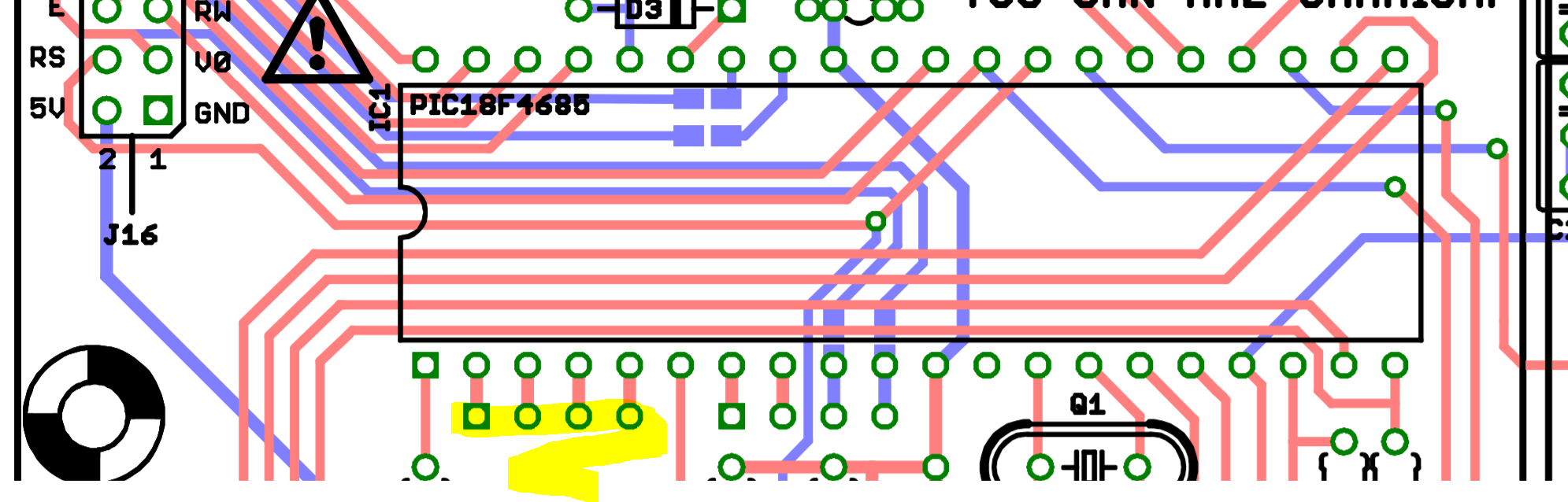
If you look at the Base PCB, they were kind enough to break out the ADC pins: : You have to enable the AINs by compiling new SID firmware: http://www.ucapps.de/midibox_sid_manual_fp.html take special note that unused inputs must be connected to ground. So if you used the first 4, clamp the 5th. I've got no idea if anything will be different for the sammich variant, as some of the pins are evidently supplying data to the LCD. I take it you want actual CV rather than pots, so you should use clamping diodes or a rail to rail op amp limiter to protect the PIC from over/undervoltages.

-
Speed up scanrate of NG by kicking out other scanroutines?
latigid on replied to FantomXR's topic in MIDIbox NG
First up, did you try to reduce the number of shift registers? Already this speeds up the scanning. -
I thought as much, just the date on the blog was August 2016, maybe he updated/migrated. Anyway, super cool build!
-
Awesome! What keycaps did you use for the Cherry MX stems?
-
Not sure if this belongs in the MbotW or here (was it posted already?), but I came across a nice looking 8 SID beast with built in Moog filters (+VCAs?) http://riversynths.com/tag/polysynth/
-
I get what you mean, but I still think separate buttons are better. Also it doesn't add cost or complexity to the UI, rather your idea would mean having to guess the function instead of glancing at what button around the wheel was lit (the 16 "selection" buttons have no labels as they're multi-use). The other point to consider is that Trig and Para each have two functions, one to edit what's actually in use and the other to select values/toggle triggers on or off. What are the internal dimensions of the Heidenreich case? Maybe it will fit but first the PCB sets have to be designed. You'd have to order your own front panel/rear panel, and it'll likely be cheaper buying a full case from Adrian rather than a one-off panel set from Schaeffer. I also can't guarantee the availability dates, so if you're in a rush it might be quicker just to complete the Wilba model.
-
Well, one provides the triggers (including all sorts of weird and wonderful stuff when you get into it) and the other gives note/CC values, chords, delay ticks etc. http://wiki.midibox.org/doku.php?id=mididocs:seq:beginners_guide:start#trigger_layers_and_parameter_layers Hopefully this layout can demystify the usage for plebs like myself!
-
It's definitely the intention to have duo LEDs for both the "soft" and "selection" buttons. The remainder are MEC illuminated ones, so every button can have an LED. Matias switches have a lifetime of 50million cycles, MEC are 10 million. This version will also have a nice case that I'm working on with Adrian. Open questions: switch on the 5V line, yay or nay? How many MIDI outs?
-
It will run on an STM32F4, TK.'s label not mine. The operation will barely be different from the Wilba model, apart from having better quality and more refined button functions (as the usage has evolved since 2008), and also the new concept of a selection row. This is the trade off for not making something drastically different, that needs development time TK. can't provide. Here's a lefty model:

-
Current state: Excuse the lame font and generic/misaligned labels! This one has fewer switches, but more switches. The idea is to use the first row of keyswitches as "soft" buttons, or General Purpose like in Wilba's. The second row of large switches are for 16 "selection" buttons. This row will change function depending on the state of the 8 buttons around the datawheel. Here you will select the track, parameter layer, trigger layer, mutes etc. As you have 16 buttons, multiple selections (esp. tracks!) can be selected at the same time. I think it can be done that if the selection button is held down, the datawheel can scroll through 1-16 of that function. On the right, the buttons below the wheel are for transport, record, live, loop etc. The smaller buttons running along the bottom edge are editing commands like copy, paste etc. and edit, menu, pattern, song, utility and so on. There's a front-mounted microSD card slot and by request a beat LED. TK. will be disappointed that the bottom row are labelled on the underside, but the (rough) panel cutout dictates this, plus the association is clearer that the round rather than the squarish buttons perform these functions. This is a rough sketch of the power/USB entry: Power switch, USB B for computer and power, USB A for OTG host (here rather connect the B port to a powered hub), and a switch to select for OTG. This way you could still perform updates over USB even if the primary use was as a host. Some sort of USB cable will then connect to the Core located somewhere in the middle. I thought to add a 3.5mm jack (or maybe 1/4") for a footswitch (via a buffer) and wire this to the datawheel board, let's see. Adrian brought up a point of switching the data and power lines, and thinking about it I don't think it's wise to have a power switch, because USB normally relies on connecting the power before the data. So is it a problem to use your master USB hub or wall switch instead? Otherwise something like this can be considered, although it seems a lot of effort: http://mcs.uwsuper.edu/sb/Electronics/USBswitch/ The DB-25 + PCB is the MBHP Line Driver. Apart from testing switches and keycaps, and routing up the main PCBs, the next question is MIDI IO. There is space for 16 DINs, but apparently it's inadvisable to use 8 MIDI ports on the same I2C buss. Instead, what's the chance of using the STM32F4 Core's second I2C? Or do we say 4 I, 4 O and 4 I2C outs are enough? There'll be provision to connect the BLM 16*16, maybe other goodies. I'm intrigued by KissBox OEM, but the PCB takes up too much panel to be accommodated here. If it was as wide as the RJ45 socket it'd be a contender!


-
Maybe post the relevant part of an NGC?