

latigid on
-
Posts
2,524 -
Joined
-
Last visited
-
Days Won
149
Content Type
Profiles
Forums
Blogs
Gallery
Everything posted by latigid on
-
DIN and DOUT actually run in parallel (according to their function) but share the same serial clock. For a wired build, you daisy chain blocks of DINX4 and DOUTX4; the newer smashTV ones should allow any order of these, but IMO it's best to split them into two distinct chains of DINX4 and DOUTX4. You count the number of shift registers of each type and define that in the setup file. Now each digital input or output (switch or LED) has a given "address" according to its position in the chain and which pin of the IC is connected. It should be okay to assign each function arbitrarily, so there's no requirement to match a DIN with a DOUT pin.
-
The MB-6582 uses a BLM (button LED matrix), I'd suggest another one of the setups (8580?) and assign the buttons/LEDs according to a DIN/DOUT chain. LEDs are controlled by DOUT, not by switches...
-

STM32F4 SDCARD Reading CID failed with status -256! Solved
latigid on replied to gerald.wert's topic in MIDIbox SEQ
Good sleuthing! Thanks for the write-up. I hope they'll send a replacement. When doing bodge repairs like this you can consider using thin enamelled wire, i.e. "Verowire" or even that used to wind transformers/coils. -
Hi, thanks for the tip! I did a fresh checkout and everything compiles okay now. Thanks again, Andy
-
Clearly I need to learn Tortoise better, I can check out to a previous working rev and my builds work again. Still, there's something not right with the current one.
-
For a few days I've been unable to build using MSYS. I get a compile error of "no rule to make target" with reference to /MemMang/umm_malloc.h Even if I go to a previous subversion the error persists. Any ideas? Best, Andy
-
Damn! The SEQ was looking so nice! Congrats on the new arrival though! I'm sure there are better people to ask than me, but I'l give it a shot. In mios32_board.c #if defined(MIOS32_BOARD_MBHP_CORE_LPC17) || defined(MIOS32_BOARD_LPCXPRESSO) #define J15_AVAILABLE 1 #define J15_SCLK_PORT 1 #define J15_SCLK_PIN 25 #define J15_RCLK_PORT 1 #define J15_RCLK_PIN 26 #define J15_SER_PORT 1 // also used as DC (data/command select) for serial interfaces #define J15_SER_PIN 28 #define J15_E1_PORT 1 // also used to control SCLK of serial interfaces #define J15_E1_PIN 29 #define J15_E2_PORT 3 #define J15_E2_PIN 25 #define J15_RW_PORT 1 // also used to control data output of serial interfaces #define J15_RW_PIN 27 #define J15_D7_PORT 1 #define J15_D7_PIN 19 you can see the pin mappings. I think you'd change these MIOS definitions, and every time a new firmware update came out, you'd have to build your own hex for your hardware. The question is then what pin can be swapped in without conflicting with any of the SEQ functions, and is it special function? Some pins are set as timers for critical processes; I don't know if the R/W pin is critical or not. J10 looks like it's free for remapping? Of course, you may have to initialise these pins first -- it's probably not as simple as substituting the port and pin in the definitions... In the case of buying a new LPC board, I think the newer ones have a different layout, so they probably won't fit into the Core headers :(
-
No definite timeframes from my side, but still likely in the near future.
-
 Thanks for the explanation!
 -
At some point it stops being an "SCS" and starts being a custom MBNG. You will get a better idea of what's possible by reading through the documentation: http://www.ucapps.de/midibox_ng_manual_ngc.html http://www.ucapps.de/midibox_ng_manual.html
-
Anybody is free to build a "V3-like" MB-SEQ using DOUT/DIN modules in serial chains. The Wilba board is a simplification that saves shift registers and wiring by arranging the LEDs/buttons/encoders on a CS, only wiring up in a matrix. There's no real functional difference between the two, just convenience and all-in-one builds are less error-prone. V3/V4 is really MIOS8 vs. MIOS32. If you want a SEQ you can: Wire up your own front panel Wait for smashTV boards to be in stock again Wait for developments on a new SEQ/case (me/Adrian) Cheapest? Most immediate. Lots of work and probably lots of mistakes Just wait. Established and good value. No case option New concept, might be a bit more expensive but an elegant solution. Timeline is six months or so.
-
Hehe, cool! For UTB OTG, I found a supply of Micro B cables terminated in a 100mil header: http://www.ebay.de/itm/Micro-usb-5pin-Stecker-Auf-1x-5Pin-Buchse-0-1-USB-Header-PCB-Hauptplatine-Kabel-/291621445358?hash=item43e5fe1eee:g:M9YAAOSw7aBVJ8cI -- you have to search to find different listings for each country... also on amazon etc. The Disco board also has a breakout for OTG, instead of a custom cable a wire to a switch with 0V/ground on the other side will do. I'll have a new USB entry design ready for the alternative SEQ at some point. Once again, cool work and I'm glad the MIDI thru drivers are working well.
-
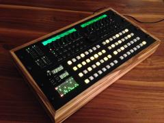
Looks great! Is the BLM 16*4 hand-wired? What switches are used?
-
FWIW I've also had issues with some PNG encoding, even with small file sizes.
-
Put it this way: you already need some sort of button scanning via a DIN (columns) and a DOUT (rows). With just one more 74HC595 register you get LEDs for "free." Note I2C LED driver stuff has already been done by Ander (Station). Just not in "regular" MIDIbox projects.
-
Yep, also you'll see the track drawn on the copper layer as well as the plated via.
-
To me, the available files show copper on both layers. Check with a multimeter?
-
Just continuing a discussion started in a pic from Sauraen. I asked if he noticed any problems driving that many LEDs, the answer was that everything worked out fine. Psykhaze asked about 74HC541, but this is implemented in the Core to take the load off the MCU driving the SRIO lines. (For better results resistors should be added at the 541 outputs to control the impedance/attenuate reflections.) Also, some degree of PWM control is possible in LED matrices but of course limited by the 1/8 multiplexing. There are LED driver chips as mentioned, but they run over SPI. The beauty of shift register designs is (as mentioned) wide availability, but from a programming perspective the usage is also very simple -- once the matrix driver is written -- just send a series of bits and latch in a regular cycle; the low processor overhead is easily predictable. While the standard BLM uses 220R /13mA peak for red LEDs, the BLM 16x16+X is driving blue LEDs with 56R, so more like 35mA peak. Of course only one 595 output will be on at a time with 1/8 multiplexing. Still, turning multiple LEDs on drops the supply voltage, so much so that I needed a power up delay to allow the logic to stabilise, and a local buck-boost regulator helped. My feeling is the "high" current demands put on the anode drivers could do with some improvement. From the current sink side, this is already solved by using NPN bipolar transistors. The row scanning means 8 or even 16 LEDs could be on at a time, but that's no problem for the transistor. An N-channel MOSFET would likely do a better job, but these are a bit more expensive with lower availability, and are more prone to ESD. Another common method is to use a ULN2803 (8-channel Darlington) current sink. The issue is the extra PN junction has the effect of raising 0V/ground, which in turn can cause problems triggering the DIN side, especially if the supply starts to sag/droop. It seems fine to use a plain old 595 output to drive LED anodes at low current. But what about higher current LEDs, or organ pipes? The simplest method might be to use a common emitter PNP with base and collector resistors. If a higher source voltage was needed, a cascaded NPN/PNP would work. (If a PNP had 12V supplied to the emitter and 5V switching on the base, it would never turn off.) Getting fancier, there are chips numbered 2981 which act as source drivers. The UDN2981 is from Allegro (availability isn't great); the MIC2981 can be ordered at Mouser with good stock levels at the moment. So maybe that's the answer. TPS2080/2081/2082 (dual) and TPS2085/2086/2087 (quad) look okay as chip-based MOSFET high side drivers. There are shift registers with better sinking capability (e.g. TPIC6595), but there's only one I've seen for sourcing: MIC5891. On paper it looks good (have to check the programming), but the pinout is different -- actually nicer than 595 IMO -- and I'm a bit wary of using "specialist" chips for long-term availability. Now I've got all of those part numbers down I can close most of my browser tabs :-)
-
Thanks for the writeup, and I second the idea of making a wiki entry. The diagram needs work, maybe choose a better-contrasting font. As well, the correct connections/mods/swaps can be indicated on a PCB diagram for improved clarity. I think someone may have done that already.
-
MIDIbox Quad Genesis Front Panel (MBQG_FP) PCB: Most LEDs On
latigid on commented on Sauraen's gallery image in MIDIbox Gallery
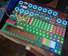 Very pretty! May I ask what current you're driving through the LEDs? Do you experience any voltage sag/droop at the 595 anode outs? The story apparently goes, that if you're drawing more than 5-6mA (continuous) through a 595 output pin, the source voltage will decrease. http://electronics.stackexchange.com/questions/77841/how-much-current-can-my-74hc595-handle-on-each-output-pin While keeping in the MIDIbox paradigm of ordinary shift register chips, one thought is to add PNP BJTs as "current sources" (moreso voltage sources due to constant current sinks on the cathodes). Any thoughts on this?
 -
Nice! To be honest, I don't think large caps do much outside smoothing a rectifier or acting as DC blockers for the audio path. They're a standard addition for any power entry (including things I've designed...) but I recall that their actual effect is negligible. Something to do with a circuit block's reactance? I think the idea is to form a low pass using the power line as a resistor, but if you crunch the numbers they don't add up. Better to implement a series inductor or properly rated resistor at the entry point, and decouple chips locally. The notion of a "reservoir" topping up the supply rail as it drops is nice but I don't think it rings true.
-
Just cut/desolder the flywire connecting the regulator output to the 5V buss.
-
Also: If you have the large caps in there, removing them or adding the flyback/Schottky diode could help.
-
Hmm, my one is 1.5A, but if others are using it okay it's a puzzle. It would be good to connect the 5V post-regulator through a multimeter to be sure on the current. You may have a sVreg that's going into overcurrent shutdown too early. Some things clamp at half the rail voltage -- could explain your 2.45V. Another possibility is an inrush current problem. Can you try to sequence the startup with the LCD initially disconnected? Is everything else standard with your build? No ultra bright LEDs or anything fancy?
