

latigid on
-
Posts
2,524 -
Joined
-
Last visited
-
Days Won
149
Content Type
Profiles
Forums
Blogs
Gallery
Everything posted by latigid on
-
:) The adafruit pads have a 3mm cavity, meaning it's not possible to fit e.g. a 5050 LED underneath. There are new components around, I'll try a search. I assume that WS2812B will use too much memory? That would be an easier way to do it if there are decent mounting strategies. There are also newer APA102 LEDs that run over SPI (clock and data) -- easier to manage? RGB and maybe even duoLED would need a 4 layer PCB, although the task is simpler with 4*8. In this case we could even consider splitting over 2 PCBs per 8*4, with SMT LEDs shining from underneath and the button pads/matrix on the top. Re: Cherry MX: that could also work with the newer clear version (MX3A-L1NB I think), though they're still not readily available as far as I can see. Buy a keyboard and bust out the desoldering gear? The caps normally have different sloping angles too, but I see the Far East has bundles for cheap.
-
I think we (you) had the idea first, but it's getting pretty close to the Deluge: Have a laugh at the Kiwi "akksnt" No, I'm not suggesting a full RGB matrix, but I do think we could "reclaim" some of the features, especially the zoom control for the 16*16. For this 16*4 version, would it make sense for "BLM duties" with only a single colour for three of the rows? I'm not sure about doing another full duo BLM, plus one motivation was to go for a shorter PCB height to fit it into 3U Euroracks. I'll have a look anyway :).
-
With stickers that might be a very cheap and effective way to label things, nice idea! Hopefully the feel wouldn't be too plasticky and the glue sticks to the silicone okay. Would be nice to send the adafruit pads to Formulor and get them to laser cut directly, can use a v1.0 BLM PCB to hold 16 at once :). I have the advantage of a 16*4 BLM already done for SEQ v4L, so I can always see if a layout is possible with all registers on one of the copies and connecting the matrices over ribbon cables. On the other hand, the registers could be split and just the SRIO chain extended. The layout and components would be present anyway, so it's just a few extra components to buy (plus the spare 0.5*595 could find use as extra LED drivers, beat LED etc
-
http://www.formulor.de/material/silicon What about little laser-cut caps with engraved labels? I think you can infill with special paint too.
-
Of course, I remember this one well :). Also a lot of horror stories about how difficult it is (not even including the conductive part)! A very important feature of the adafruit/sparkfun pads though is the little guide "nubs" that sit inside PCB holes and stop things wobbling too much. Okay, if the general idea is okay we can consider a rubbery one and a rigid one.
-
I know they make a "long life" version of TL1100, but you have to pay for it :). Switches are just damn expensive, especially for nice-feeling ones. The rubber buttons are nice to play and do have a bit of a "click" as well. Plus, they can light up when pressed. I think the technology has improved since (vintage?) Roland keyboards. It's not a greasy graphitic substance but something that feels well integrated into the rubber. If you tell me the switches you're after (Marquardt I suppose ;)) I can see if it's doable to make a multi-format pad. Best, Andy
-
Curious that you mention it, because my biggest complaint about the SEQ is that the TL1100 switches commonly used are pretty crappy and exhibit problems on mine. The BLM on the other hand is still going great after a year. Do you have a specific poor experience/anecdote to share? All of my PCBs with conductive pads use ENIG plating, which should last much longer than HASL. If there were contact problems, I don't think it would take more than a quick wipe to clean them. In any case, it's not intended as a replacement to the Wilba board, just an alternative concept.
-
Agreed with TK. on the one-handed edits. The layout looks nicely symmetrical, but I think the centre will be a bit too cramped. Should tracks and groups have some sort of indication, or is it okay to just read the display? If the idea is given the go ahead, users could choose how to mount the extra encoders. Perhaps a little PCB is even unnecessary; the DINs could be fly-wired to panel mount encoders. Also agreed about proper labelling, and it's a crucial factor. A few points: GPs might be labelled above the switches, the bottom row below -- would that look weird? Due to the extra spacing required to match encoders, there's more room between columns of buttons. Some functions can be labelled vertically instead (if not too strange). Some things are done with symbols already, we could consider more icons e.g. copy, paste etc. For the BLM 16*16 used the recommended panel cutout. I think it would actually be okay to make the hole a few mm smaller = more room for labels.
-
That's also a good possibility, my idea was that when turning the encoder the display is updated with the appropriate layer. Admittedly I'm guilty of under-utilising trigger and parameter layers, so I don't really have a feel for the work flows. EDIT: I see that there needs to be a distinction between selecting a layer to edit steps and accessing the "layer C" setup, although there's a separate GP menu for TRIGGER, and parameter layers are edited from EVENT. Or, an encoder+switch for the best of both worlds. Click to choose one of track/trigger/parameter layer, turn to select (or use GP buttons), click to exit. 3 encs + 3 switches is 9 DINs though...
-
Sure, it's clear that the buttons select the "cursor step" which is adjusted with the encoder. Hey! I thought you wanted to save space ;). On second thought, BLMs are probably best for extensions. For a start, you kinda need two colours per step, which this matrix doesn't do. The GP buttons (top row) are also used to control gates, so how do you differentiate between editing a position and turning the step on and off?
-
I for one would prefer the full set of encoders, as to me they connect the knobs and displays together nicely. I'm sure the SEQ can use the concept of a "cursor" on the LCDs to invoke the datawheel, although you'd have to think how that works with the remaining UI. Vertical height is another point of consideration but at the moment I'm thinking panel mounted LCDs/OLEDs (slimmer) that overlap with PCBs, depending on what else needs to fit, mounting holes etc.
-
Did you mean the horizontal should be 1/3 less? In my quick mock-up with boards pushed together, the total width is about 378mm (compared with 421.64mm for Wilba's). In reality the limiting factor are the LCDs (182mm each standard), so I don't think a 1/3rd reduction is possible. Personally I don't think fewer buttons are a good idea :). But for some ideas you might check out the v3. Note in the HW config file it's easy to assign most functions to custom mappings, so even in a generic form you could leave out some of the functions. The coding question boils down to whether TK. will support splitting the matrix into 2*8*4 and adding subtle extra encoder/"group" handling. If yes, the PCB routing will be so much easier, also smaller boards are much more convenient to ship. I did check these out, sadly the spacing is 25mm, which looks weird aligned with the buttons.. Also the cost is double the adafruit price. Fun fact: if all buttons were there with LEDs, a new performance mode of a 16*3 BLM would be doable. Let's keep talking, it's much more interesting than forum tumbleweeds. :)
-
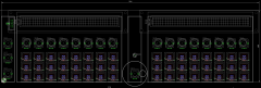 Yep, the vertical spacing is the standard 15mm, the horizontal is 19mm to align with encoders. The pads would move around less if they were in blocks of 4*3, but strips of 1*4 at least hold together okay in the BLM 16*16 (an acrylic spacer helps). Just throwing a concept here, nothing's concrete.
 -
SEQ concept using illuminated buttons in place of tact switches/LEDs.
-
I think it was mainly a collaboration between Wilba and TK., heavily influenced from the v3. Here's what I came up with on a Sunday afternoon: The CS would be spilt over a few PCBs in order to save costs. Note the four extra buttons where the encoder wheel is, they wouldn't need to be installed and the whole thing could be tighter. The smaller boards are identical too. I would wire each main board as an 8*4 matrix, using the spare 4 DOUTs for the beat LED and maybe three LEDs/one RGB LED (top left). This way the RGB hue could indicate the track group as in the current v4, or OFF/LED1/LED2/LED3 as groups A-D. Probably SMT with all registers on board. There could even be enough space to PCB mount the other panel hardware, i.e. built-in MIDI IO etc. I kept the 19mm spacing for encoders, sadly the adafruit illuminated pads have 15mm spacing, so it looks a bit weird connected together. I think separating them out is a good compromise (hopefully stable enough). The whole thing could be <110mm = Eurorackable. Every button gets an LED, even if they're not used. One issue is the lack of space between buttons makes panel labelling in the horizontal direction a bit hard. Need to check the resolution of Schaeffer's laser printing :). Or, the labels could be done vertically instead. Interested to hear your ideas. :) And probably more importantly TK.'s.
-
© 2016 latigid on
-
A query, perhaps for v4+: would it be possible to handle track selection (1-16, not in Groups), trigger layers and parameter layers with 3 encoders rather than button/menus? If I was to design a new SEQ CS (just an idea for the moment) the left-hand buttons could be swapped out, reducing the overall PCB height = cheaper.
-
We're getting quite philosophical here :). From the deep history of MIDIbox, there was a time when designs were much more open and it caused untold problems. Most of the old guys are no longer around, so it could be a chance to start something different. Nowadays, MCU projects are all over the place, with many different options of build complexity and price. A hardcore MIDI controller is less attractive to DIY when equivalents or "better" can be purchased for cheaper than parts cost. The advent of all-in-one PCBs has killed off a lot of creativity, e.g. MIDIbox of the week. Having organised a small but costly Bulk Order, I can understand why people choose not to open source everything. It's hard to explain, but you do feel like you have ownership over the IP due to all of the blood, sweat and tears put in. A different line of thought: by designing something, what's the obligation to keep a supply line running? Even big businesses sell "limited time only" products. I'm not advocating this approach, but as this is a volunteer community, you have to keep active and take the opportunity to buy PCBs/components when they're available, and support those who put the time in to design and organise orders. It's the responsibility of members to participate, otherwise the place turns into a ghost town. As a corollary, it's disheartening when something's promised and not delivered, more so when money has already been paid in. At the very least, anyone selling PCBs or projects should seriously consider a succession plan when they might no longer be around. Even if they don't send a cache of gerbers to TK., something like having the files somewhere accessible and backed up, ready to send on or be quickly uploaded to the wiki. Another concept I just noticed from a post on MW is "donation ware." The source files are open, which means anyone can simply upload to their favourite fab. They take responsibility of shipping, customs and quality, and can on-sell the remainder they don't need. It's essentially open source, but with a gentle reminder that it is somebody's work you're benefiting from. If you appreciate it and want more from the designer, you can send them a bit of cash to say so. While the price breaks get worse, and it's more energy and money for lots of small packets, this chops up the task into many small parts and relieves pressure from the designer. It also emphasises that this is a hobby community, not an evil profit-making business.
-
Documentation now online on the wiki: http://wiki.midibox.org/doku.php?id=seq_v4l_mk._ii
-
What rev of PCBs do you have? The smashTV DOUT already connect the appropriate SI/SO signals, so in theory you can have any arrangement of DIN/DOUT. I can't say about the other modules you've got though. In old MIDIbox days, J8 and J9 were on separate "SIL headers." It's also possible to wire your ribbon cable with a third DIL connector and split DIN and DOUT Y-cable style (I understand this isn't your usecase). Have a read through the forum though: others have had problems unless the TPD is last in the chain because it has an unbalanced sequence of 165 and 595 chips. Reduction in signal transmission of (I assume) SC and maybe RC led to hang-ups. Again guessing, but adding yet another PCB, cable, connections doesn't sound good. Then again, the receiver side may give a decent drive that solves the issues. Try and see? And let us know?
-
I like the refined concepts on chords and drum tracks! Considering my previous request: I think this can be worked-around by using a SKIP trigger layer, so I will give this a go and see how easy the handling is.
-
Probably You might want to check if you can use the USB ports and "re-flash," but I'd say she's a gonner. I think if the ST link side still works you can use it as a standalone programmer.
-
Hi, Yes, I have PCBs available, please PM for details. No PCBs left for now. I may consider doing another run in the future. Best, Andy
-
It would be helpful to list the actual PICkit clone first (+ pictures). I use the DIAMEX one recommended here with flying connections (no external voltage) and simply buss powered from my computer. I also went for auto-detect Vdd level (choosing the correct family will ensure this).
-
Okay, I'm glad it works now. Turning it off and on again is usually a good thing to try :). Often CMOS needs powering down because they're in "latch up" -- a fault condition that can only be resolved this way. Or just resetting the SRIO data etc. Happy building and learning!

