latigid on
-
Posts
2,524 -
Joined
-
Last visited
-
Days Won
149
Content Type
Profiles
Forums
Blogs
Gallery
Everything posted by latigid on
-
I loaded up ain_jitter_mon to check the performance of AIN_4: Test conditions are a 5V reference into the input (normalisation), attenuation of this to min/mid/max using the on board pot (this pot doesn't go all the way to 0V/ground to protect the TL072 op amp output). AIN4-7 are jumpered to ground at the Core. Each point is a 1 second sample with the difference between maximum and minimum value plotted. ADC resolution is full 12-bit, so even with a jitter of 20 it's ~0.5% error. I think that'll probably be acceptable with CV inputs that are changing over time. Apparently there's also the possibility of oversampling. For reference, the figures look pretty similar to simply connecting a pot to 0V/3v3, so my guess is that the STM chip is the main culprit for noisy ADCs :).

-
Aha, might have been indeed! Thanks muchly for the insight.
-
Probably unrelated, but I'll mention it -- the other day I was trying to create a new file via MIOS Studio File Browser called "AOUT_TEST.NGC" and it wouldn't let me. But I could create a file called "AOUT.NGC" Apparently this SD card has some corrupt sectors on it (when used in a camera), so it might work better on a different SD?
-
Hmm, I think Altium will cost you over 9000 dollars, unless you're a student. There are cheaper options like EAGLE (freeware up to a certain PCB area), KiCAD (free and open), Diptrace etc. All CAD software has steep learning curves. Plenty of fabs to get your boards done all around the world. Where are you located? If you're planning large boards, they won't be cheap and you'll have to buy multiple copies. Modulbox is a preliminary ideas page from @Psykhaze. I'm sure he'd be happy to discuss with you if there are common points of interest.
-
Schööne Demo! Accent is mostly quite okay for me ;) It's great to see how comfortable you are with the setup, and you have a wide range of sounds available. What's the next plan with the band? GIgs? Recording? Or just more fun jams?
- 3 replies
-
- 1
-

-
- doundmorph
- beatstructure
- (and 1 more)
-
http://x0xb0x.cvs.sourceforge.net/*checkout*/x0xb0x/hardware/mainboard.brd?revision=1.1 YMMV Are you self-etching the PCBs or sending them to a prototyping fabricator?
-
 Top board (blue) is 108mm tall, bottom (green) is 100mm. The wooden box is an old wine case that happens to be about 133mm as the outside dimension. Inside is ~110mm, so a good facsimile for Euro rails.
 -
Thanks! Still needs a panel though ;)
-
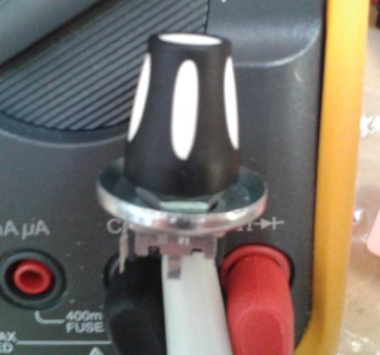
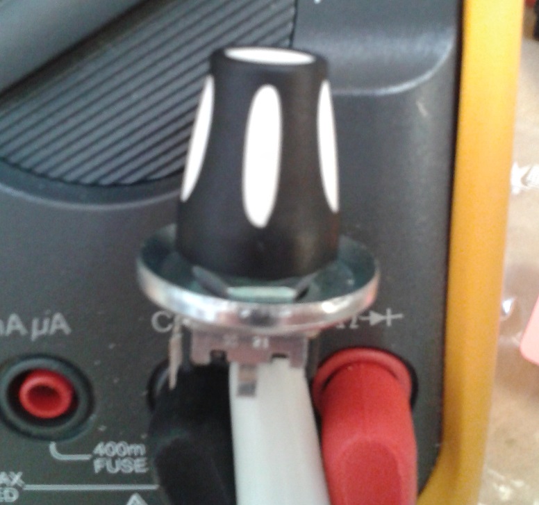
Both AIN_4 and AOUT_4 are working nicely :). The range switches are especially useful for AIN, but I can see the benefit of alternative AOUT ranges with improved accuracy when used as a mod source (rather than a pitch CV). It seems a good idea to use the bipolar option for pitch, otherwise you'll always be transposing. E.g. I think C0 in MIDIbox land is set to 2.00V?
-
-
-
From the album: AOUT + AIN + EURO
© 2016 latigid on
-

sammichSID Bulk Order Run #29/#30 - preorder form online
latigid on replied to nILS's topic in Bulk Orders
You're lucky nILS isn't here, or he'd probably charge a stupid question fee (or make a snide remark) -
Here's some more! *** Hi, the hardware/case is usually the most expensive part, so you should ask yourself what you're willing to spend. Quality normally correlates with price. You can get a lot of parts from Tayda in Thailand, e.g. Pots (5-10k are good values) Switches (take your pick, normally you want momentary ones, perhaps some toggles or rockers. While cheap, these are considered to be quite poor quality, e.g. the moulding resin tends to melt very quickly during soldering.) It's simple to order under the customs threshold for the EU and you'll normally get your parts within 1-3 weeks. Check on their Face* page for a ~monthly discount of 10-15% http://www.banzaimusic.com/ (Germany) http://www.watterott.com/de/Komponenten/Mechanisch/Schalter-Taster (Germany) http://smallbear-electronics.mybigcommerce.com/ (US)
-
To clarify the above post: if J2 is used for power, then J17 should be open. For externally powered Cores, I recommend (and will likely consider) the following style of cable (YMMV, not tested yet): http://www.ebay.com/itm/Right-angle-OTG-Micro-usb-B-5pin-male-to-A-female-panel-mount-Screw-Cable-25cm-/381713301841 Heh, just for fun, these are the shipping criteria:
-
There's another jumper that interrupts the power supplied from USB (J17), so for external supply, J17 should be open. If USB host is unstable, try unbridging the jumpers as described above.
-
Initial doku for AIN_4 is online: http://wiki.midibox.org/doku.php?id=ain_4
-
Is your shift button pulsing each quarter note when the sequence is running/ illuminated when held down to change modes etc.? I'm using an F1 Core, so it could be related to that. Did you configure the routing from the MIDI menu? You have 16 nodes to play with. What do you want to send where?
-
After v4.091 I believe the shift button LEDs on the BLM 16*16+X no longer illuminate. I think this was the case on Saturday, but I can't test today due to my SD card being lost in Munich =). At least with the BLM in test mode the lights work without issue.
-
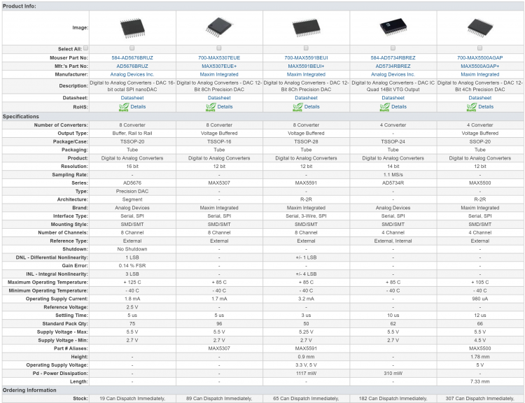
Sure thing, hence "not impossible." Everyone can go ahead and design their own DACs, but if there's something similar or even equivalent to one of the existing DACs, integration into MIOS should be easier. E.g. if MAX5500 follows the same code protocol as MAX525 (I need to check), then nothing has to change and it's hopefully no extra work for TK. If the pinout is the same, then I just need to get a chip + adaptor and test it in the current PCB (or Altitude could try with his AOUT boards already prepared for SSOP MAX525).
-
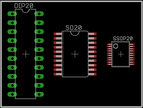
(T)SSOP plus an adaptor is a good idea. I'm not sure if pre-soldered products may be sold in Europe(?). I would prefer to keep the chip coupled as closely as possible to the PCB (+1 on the dual use pads), but it looks like time is up on DIP DACs as you say. Quad vs. Octal: I'd like to keep the quad layout if possible, although it could be doable to have an octal DAC and two quad control panels. If I can avoid re-routing the DAC board too much I'd be happy :). Hopefully you can read that. MAX5500A: Quad 12-bit ±0.25 (worst case ±0.75) LSB integral non-linearity ±1 LSB differential non-linearity 3.5mV offset error 6 ppm/C offset-Error Tempco Typical -0.3 LSB gain error 1 ppm/C gain-Error Tempco Similar pinout to MAX525 -- in fact looks basically like the same die as MAX525 AD5676B: Octal 16-bit ±1.8 (±3 worst case) LSB integral non-linearity ±0.7 LSB differential non-linearity ?0.75 (worst case ±2) offset error some other parameters are given as percentages cost is the same as 2* 5500 chip layout is a clockwise arrangement: a bit annoying to keep the same order (A B C D || H G F E) not impossible. MAX5590B 'A' variant is not recommended for new designs... not a good sign Octal 12-bit ±2 (worst case ±4) LSB integral non-linearity ±1 LSB differential non-linearity 5/25mV offset error 5 ppm/C offset-Error Tempco ±20/±40 LSB gain error(? 2/4?) 1 ppm/C gain-Error Tempco chip layout is a clockwise arrangement: a bit annoying to keep the same order (A B C D || H G F E) AD5724RBREZ Quad 12-bit ±1 LSB integral non-linearity ±1 LSB differential non-linearity ±6mV offset error 4 ppm/C offset-Error Tempco 4 ppm/C gain-Error Tempco actually a better pin arrangement expensive Once the parts arrive I will need to test the MAX525 AOUT to see if the scaling circuit works well in general. Then we could consider an AOUT_3G (?) module.
-
AD5734
-
By no means is it impossible to solder SSOP, but the difference in pitch is significant:
-
MAX5500 (SSOP) could work.
-
I see two problems with the DAC8565: no DOUT for serial chaining, and TSSOP is fairly tedious to solder. Those 4 extra bits aren't too useful considering the error of.. 4 bits! I'm fine with designing and testing a replacement if one exists!
-
We can do better. This was my idea as a touch sensor for acceleration, but in the end I think the cup washers are a bit big: Albs make a clear version of this which looks really nice when illuminated: