latigid on
-
Posts
2,524 -
Joined
-
Last visited
-
Days Won
149
Content Type
Profiles
Forums
Blogs
Gallery
Everything posted by latigid on
-

SEQ with Wilba PCB assembly issues - buttons not working :(
latigid on replied to keves's topic in MIDIbox SEQ
Something else to check is the orientation of resistor networks, they have a dot which must align with the PCB legend. To test if the chip survived, you could try to swap some around and see if you can get a bit of functionality. Depending on the buttons you ordered, it is still possible to misalign these by 90 degrees. -
I found a few (old, like 25 y/o VSOP!) "Eurorack" PSUs. Not in the modular synth style but built for DIN rail electronics. They offer 5V 3A and +/-12V 0.3A. It's a linear design with a large transformer and heat sink, but uses LM723 as a precision rectifier and driver transistors to boost the current. I should really replace the old caps but at the moment it's running the SEQ and BLM just fine. Model is TRACOPOWER TCP531
-
If you need, I suggest ordering from Sparkfun et al. Instead I'm working on a different concept using hollow shaft encoders and WS2812 LEDs arranged on a PCB. This should be more flexible in terms of multicolour possibilities, also the PCB routing is much easier!
-
I don't see a schematic for the SEQ v4 lite. But one trick I found for the BLM is that Schottky diodes from the base to collector help to turn off transistors faster and can reduce ghosting on the current sink side. Also in my case there are 10k resistors from the base to the emitter to reduce power draw, and to provide a current path if the base is ever in a high impedance state.
-
Wrong topic?!
-
A problem... and a solution. Testing the BLM the last couple of weeks I was getting intermittent behaviour. Notably the SEQ was having trouble communicating at power on and the miniCore would reset if too many blue LEDs were lit. I think what happened is large spikes were causing the supply to drop out, which might appear as a reset pulse on pin 1. The problem remained if I used different 5V PSUs (switching and linear) and adding extra caps to smooth the rail didn't help. TK. managed to get all of his LEDs lit without any comment, so I can't rule out that it is particular to my build, or is caused by faster switching due to the Schottky diodes that I added. I'm interested to see how others go with their BLMs. The power situation is not ideal. Running everything connected to the DIN cable means there's quite a lot of cable impedance/inductance and the regulation is far away. Using 5V means there is no headroom for a normal regulator, and as the Quad IIC board uses the same rail to drive the MIDI IO circuit, using a higher voltage here isn't really feasible. One option is to use the extra case holes to connect a higher (e.g. 9V) DC input, then regulate down from there. A simple regulator could be built in the "muck" area present at the top (but beware that the acrylic spacer sits over the other side of the PCB). Or, continue to use the 5V line from the Quad IIC board but with a regulator injected in. 5V input means you need a "Buck Boost" converter. I bought an adafruit "Verter" board, which are around $10. I thought the simplest place to put it would be in place of the R1 bridge wire, but the problem is really on the miniCore side. So I cut the 5V and ground lines coming in after the DIN socket. For mounting I used an SIL header in the blank muck area; there are some unused functions on the Verter PCB like enable etc. I only had one terminal socket handy so I soldered directly to the output. The result is much better: the BLM initialises as soon as the SEQ is ready and there is no problem illuminating all LEDs. The Verter specifies that its normal 5V output is actually 5.2V, which is still fine for the PIC and its analogue inputs. This also helps with the inevitable voltage drop observed when many LEDs are lit. Happy BLMing! Someone asked about power draw (also added to the first post): Using the Verter, standby voltage and current is 5.2V and about 30-60mA.With all LEDs lit (both colours) the draw goes up to 647mA, although this would never be done in normal operation.In track mode with all 16x16 blue LEDs lit the draw is 467mA and the voltage drops to 4.72V. I don't really perceive a difference in brightness, but it could only be a good thing! As long as the ADC inputs are scanned relative to the supply voltage you shouldn't lose control at the top end.
-
Other way is just with four of these: Make sure not to jumper the +5V line!

-
The performance of Arduino-based controllers is generally worse than many of the alternatives e.g. Raspberry Pi etc. I haven't tried running the STM32 F4 Core in Host mode with a computer connected or not. The STM32 F1 Core works just fine standalone. For your wiring question: you have all the info you need in the schematics. As you choose to use a non-standard method (would be very simple with the carrier PCBs) you will have to join the dots yourself.
-
Duophonic keyboard? In keyboard mode, hold two X column buttons to select two tracks e.g. 1&5 (aka G1T1 and G2T1). Track 1 is controlled by the top 8 buttons, track 5 by the bottom. Damn, I'm not sure how the transpose works then!
-
Congrats on the build if all is well! You need to first burn a virgin PIC with the MIOS bootloader. After you can send it regular MIDI data using MIOS Studio. The easiest way is with a normal 8-bit Core because it has standard MIDI ports. The update is possible if you have your SEQ ready to go with the DIN cable and everything, just configure the router page using e.g. USB2->MIDI3 and MIDI3->USB2. Select USB2 as the MIDI in and out on MIOS Studio and you're talking to the Core8!
-
Lifetime is given as 500k cycles to retain contact resistance (<100mOhm increase) and operating force (+/-30%).
-
Hi Michael, Here you can find more info and pin assignments: http://www.ucapps.de/mbhp_core_stm32f4.html http://www.ucapps.de/mbhp/mbhp_core_stm32f4.pdf You will have to close the MIDI current loop: http://www.ucapps.de/mbhp/mbhp_midi_io.pdf You can see it should have an optocoupler on the input side, and series resistors/pull up on the output side.
-
The last lot of samples cost me $150 to ship... so I have not yet tested the action. This one has an operating force of 180±50gf and a switch travel of 0.2±0.1mm. So very much like the standard SEQ switches.
-
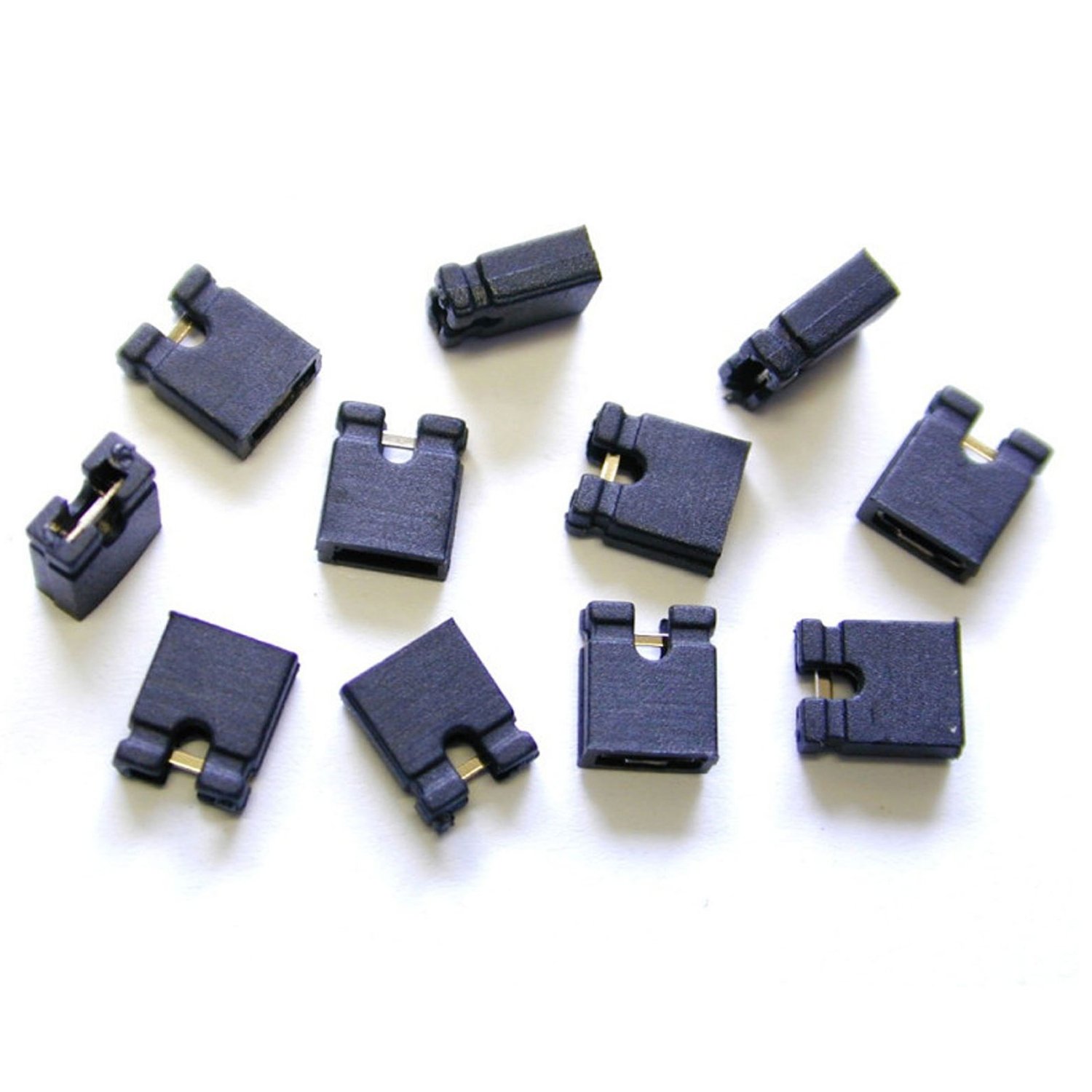
I will soon be ordering some custom parts and I thought it might be a good opportunity to get some special switches at the same time. This is an RGB tact switch with a common anode. The key specs are: Brightness (RGB) 320, 300, 110 mcd, so similar to the LEDs used in the BLM. Viewing angle: 120 degrees. Lead spacing: 4.5*6.5mm Cap dimensions: 7.8*7.8mm Pricing is not fixed yet but could be around 2-2.50 USD per piece. Please indicate any quantities that you would like. It's not a commitment to buy, it just gives me some idea during the order process.

-
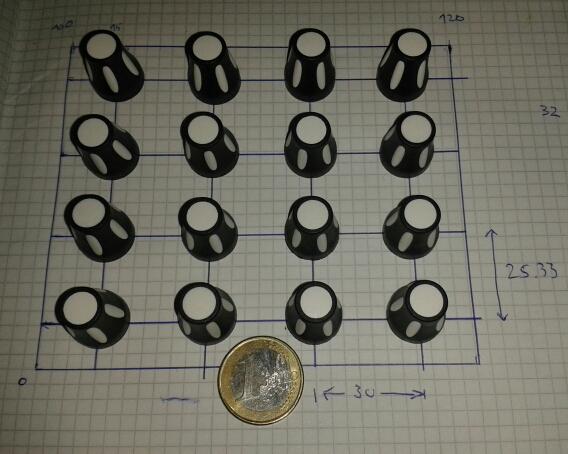
Suggested spacing for the 4x4 encoder bank: 30mm horizontal 25.33mm vertical. This should fit on a 100x120mm PCB (3U friendly). Or is it a bit tight?
-
Hi George, You want to wire SO (serial output) from the Core to SI (serial input) on the AOUT_NG. The top row of J19 is: Vs Vd SO SC RC1 0V, 5V, serial out, serial clock, chip select 1. J1 on AOUT_NG is: Vs Vd CS SI SC 0V, 5V, chip select, serial input, serial clock. You can see how the chip select jumps into the middle and pushes SI and SC over. So wiring up an IDC like I showed is one way around this mismatch. You could still use this cable with the line driver board ignoring the JAOUT header.
-
2*Core8 running MBCV. 2*AOUT_NG for 16 CV. 5V gates come from Core J5 I think. MIDI out1 to MIDI in2. Should be able to set up a MIDI merge.
-
Good to know! I'm obviously not using the line driver boards.
-
Easiest way to do it quick. Here the black wire is pin 1, brown is pin 5 6 but the right-most. This cable is 1:1 on the Core, probably simplest to wire the line driver straight and yoga after. The top row relative to the guide nub contains the serial output (SO) and so should connect to the AOUT data header.
-
Have you tried connecting the AOUT_NG directly to the Core? Keep in mind the non-standard pinning! that the pinning is not 1:1.
-
That's really nice of them to give you the circuit diagram! I had a look too, I think the reset pulse is only generated on power up once the input voltage is stable and the zener diode starts to conduct. So fiddling with U20 is the correct way IMO.
-
Any further thoughts? Is the concept workable/what people want in MIDIbox CV? I think at this stage it will be a good idea to create several small PCBs, that way the component heights are not so critical and it's more flexible (can even be used in other MIDIbox projects). I've also looked at getting RGB tact switches. The tricky part is still the OLEDs, I want to get them very close together which is difficult with the breakout boards. More expensive too. Soldering the 0.7mm ribbon is known to be troublesome but I'll try to find a way.
-
Alternative to LED encoder rings: illuminated red-green encoders?
latigid on replied to latigid on's topic in Design Concepts
Okay, I have the encoders and a 5050 WS2812 LED to test. The problems is that the LED is around 1.65mm tall but the clearance underneath the encoder is only ~1.1mm. There are a few ways around this. First, you could solder the encoder in "proud" i.e. raised up above the LED. The neatest way would be to rest the PCB flat against a work surface, insert the encoder and solder from the top. There's a slight risk that your encoder doesn't go in straight. Second is to use a washer as a spacer. Nylon is best for non-conductivity. Trouble is there are no washers of the right size. M5 is good on the outside (10mm) but too narrow inside (~5.5mm). M6 is just too small inside, M7 doesn't exist and M8 is far too wide on the outside. We need a washer with 7.5-8mm ID and 10-11mm OD. 2mm thick is best, but 2*1mm would also work. I tried to drill some M5 washers to 7.5mm but the bit chewed up the plastic. I also looked at imperial sizes, 5/16" is fine but 1/2" OD is too much. An O-ring would at least be thin enough but to get the right height you need 2mm cross section/thickness (stacking them would be difficult). So then we have 7.5mm ID and 11.5mm OD which might just work. I also worry about the lifetime of rubber products. Lastly one could get pieces of 2mm acrylic laser cut; they could even be square to save on machine time. I wonder about the expense of this though. So, that's where I'm at at the moment, if you have any ideas please feel free to share. -
BLM 16x16+X PCB and case order [CLOSED/waitlist]
latigid on replied to latigid on's topic in Bulk Orders
Waitlist: taximan (PCB+Case) -
Did you try to configure the port as AOUTX as opposed to a MIDI or USB channel?