latigid on
-
Posts
2,524 -
Joined
-
Last visited
-
Days Won
149
Content Type
Profiles
Forums
Blogs
Gallery
Everything posted by latigid on
-
Still just a semi-amateur PCB designer here. 45 degree bends aren't actually needed, this is a bit of a myth. Maybe when your signal starts to get into the microwave GHz frequency it helps, but probably not relevant for our sort of application. Maybe with press'n'peel layouts or CNC routed PCBs there's an added advantage? But I do it anyway as it helps me to keep track of where things are and will take up less board due to "cutting corners." What is important though is the type of signals overlapping. If you had a high impedance audio line running under a clock for example, that would be bad and you would likely get crosstalk. Ideally you should strive for as little overlap as possible between layers, with solid ground planes poured underneath. This is especially important when the signal is fast, long or needs good transmission, such as a clock or digital data line. In your example above I'd definitely go for B.
-
Your MIDI interface is probably not suitable; MIOS has a rigorous loopback test (?) that won't properly upload firmware unless the connections are solid. Check here: http://www.midibox.org/dokuwiki/doku.php?id=midi_interface_blacklist
-

BLM 16x16+X PCB and case order [CLOSED/waitlist]
latigid on replied to latigid on's topic in Bulk Orders
They are two separate boards, but of course I will supply both. With the case it's up to you, but you have to think about more than a whole lot of holes. $270 (or whatever it will be) sounds like a lot, especially with no engraving, but for the work you get it's very good. You need; blind studs (preferably stainless), precision milling, threaded holes, and people are pretty happy with the powder coating because it looks great, is scratch resistant and leaves no fingerprints. The other consideration is material strength. The case I designed has bends in it and several attachment points which significantly strengthen the front face towards flexing. I think the case size is "just right" for playability and more suitable as a standalone instrument that can be optimally positioned in a musical setup. Of course you'll want the SEQ nearby for editing, but with one case you're then moving to a very large (= flex-prone + expensive) panel. The SEQ button spacing is about 19mm, while on the BLM it's 15mm, so you should also consider the aesthetics. But if you're good at mech engineering and can think of a good solution it would be interesting to see. Not quite! Dimensions are about 27*28.5cm. I may be able to get the spacers cut more cheaply, watch this space(r)! -
BLM 16x16+X PCB and case order [CLOSED/waitlist]
latigid on replied to latigid on's topic in Bulk Orders
Hey, let's see now ;) At least it would make sense for EU peeps, as it would split the customs + VAT cost. For the US though? Best if I try to put a price on it and we go from there. -
You could just add a 1:1 header, it's easy to find crimpable DB connectors. Not as bad as soldering 25 pins :). Panel would differ though.
-
BLM 16x16+X PCB and case order [CLOSED/waitlist]
latigid on replied to latigid on's topic in Bulk Orders
001 taximan pcb case 002 blatboy pcb case parts 003 Macotronic pcb case 004 lukas412 pcb case parts 005 Hawkeye pcb case 006 u-link pcb case 007 nebula pcb case 008 synaptech pcb case 009 Phatline pcb 010 gidien pcb 011 Karg pcb case 012 Doc007 pcb case 013 Richie pcb case 014 arumblack pcb case parts 015 pat_00 pcb case parts 016 monokinetic pcb case parts? Please update as necessary -
BLM 16x16+X PCB and case order [CLOSED/waitlist]
latigid on replied to latigid on's topic in Bulk Orders
Welcome back! Prices are more or less the same but to confirm. Cases were $270 I think, main PCB $75. Hmmm, 20*300 = 3 full reels of LEDs... Maybe I could do a kit? Just rash thinking, again nothing confirmed. -
Mixed DIN/DOUT board -- clock and latch chaining?
latigid on replied to latigid on's topic in Testing/Troubleshooting
Thanks for your feedback. Some thoughts in reply: I see what you mean, but that would involve a layer change of either +5V or the caps. At the moment the IC pin/socket acts as a conduit. It adds a few vias, but I think you're right. I was wondering whether a plane break would actually help to decouple the longer signals running to J8/9A Not a biggie, but I straightened them. But moving the traces to the left means SC starts to intercept the isolation for the caps = plane break. This would have intercepted the +5V line, but I found another way around. Again, I appreciate your input. Best, Andy -
Which BLM driver to use for front panel?
latigid on replied to Sauraen's topic in MIOS programming (C)
Not knowing much on the programming side, I would take the SEQ and MB6582 as examples. It looks like encoders are assigned to blocks of DIN, I'd guess the matrix scanning is more efficient this way. My approach to MBCV is to have a separate SR board because; a) it's an assembly of multiple PCBs, b) there's no room on the CS, c) it makes troubleshooting easier, and d) the data lines are confined to a smaller area and should maintain better signal integrity. That said, SRIO in MIOS-land seems quite robust and easily spreadable across multiple modules, so if there's a single PCB solution it's probably the thing to do. Best of luck! -
BLM 16x16+X PCB and case order [CLOSED/waitlist]
latigid on replied to latigid on's topic in Bulk Orders
Keep 'em coming! 20 would be a good number if possible, because I'm sure some will drop out as circumstances change. Depending on how much time I have I can consider stocking some of the components/hardware, no promises though. For now it's definitely on for the BLM PCB, miniCore PCB and machined case. -
Mixed DIN/DOUT board -- clock and latch chaining?
latigid on replied to latigid on's topic in Testing/Troubleshooting
Well, it's still not too clear what you were proposing about the ground plane, but I changed it anyway .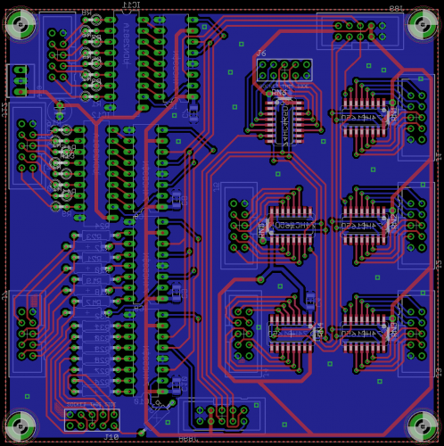
-
Mixed DIN/DOUT board -- clock and latch chaining?
latigid on replied to latigid on's topic in Testing/Troubleshooting
Did you mean the 2981 chips? They will provide level-shifted gates as part of a MBCV v2 control surface (here). There could be other uses though, like a more generic NG build. -
The wiki does tend to get neglected though. And new users generally don't have write access... While the BLM is a much smaller project, I think the concept of a "build thread" is nice as it's a chronological sequence :) of information. The OP, as long as they're planning to stay for a while, can update the first post to separate the good info from general chatter. It also seems more inclusive as there's a real discussion of ideas and problem solving. That said, it's a really good idea to backup the data to another location. A good example was the Great Muffwiggler Outage of 2015, where after a hacking incident the owner was so very close to giving up on months (years?) worth of invaluable posts until a brave knight came along and worked on a restore process. Lesson: backup your backups!
-
Mixed DIN/DOUT board -- clock and latch chaining?
latigid on replied to latigid on's topic in Testing/Troubleshooting
Could you be a bit more specific about what you don't like about it? It should be possible to mirror the 5V trace to allow a a solid connection back to the supply, but it's always a toss-up between as few vias/layer changes as possible. -
Mixed DIN/DOUT board -- clock and latch chaining?
latigid on replied to latigid on's topic in Testing/Troubleshooting
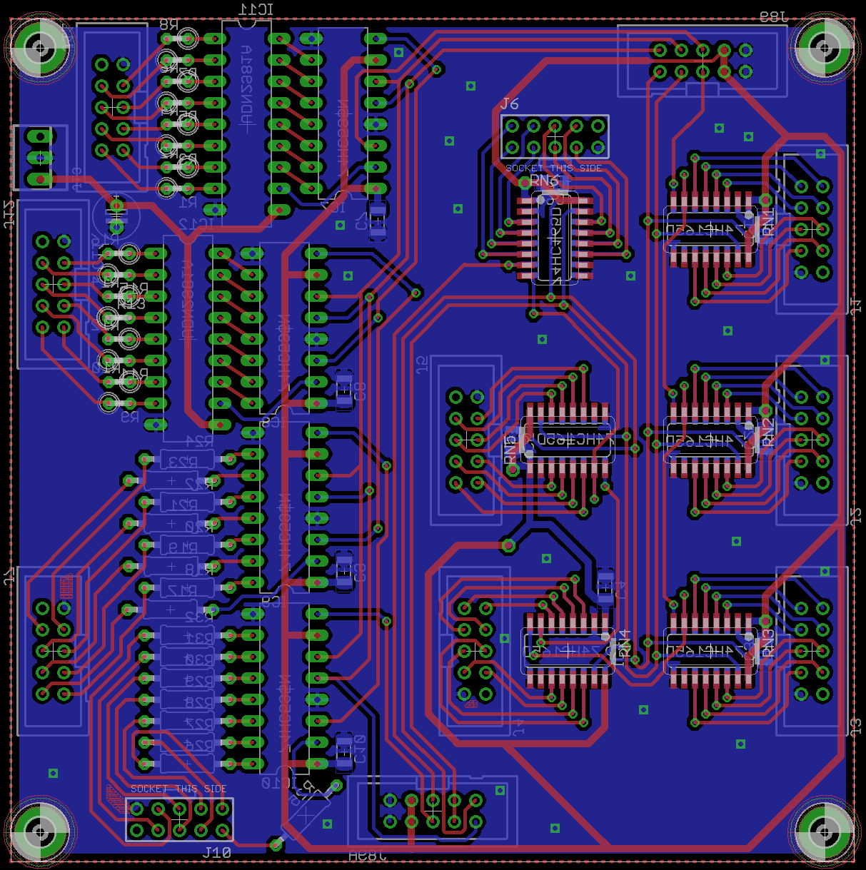
Here we go: This was my best solution to routing up the DINs. Looks like it will be possible to make a "mini-DINX4" at around 50*50mm in the future. -
Très beau!
-
 Many thanks!
 -
Okay, here's the three boards routed up: 4*4 matrix using WS2812s and Sparkfun button pads CS board with 29 buttons, 4 OLEDs, space for a CLCD (more likely a 2*20 OLED) and 4 encoders -- with push switches or WS2812 depending on the configuration. -- it's even symmetrical = lefty friendly! 4*4 encoder bank, also illuminated It should be possible to use common DIN/DOUT boards, but to make things simpler I've made another board with 6 DIN, 4 DOUT and 2*5 headers which line up with the ribbon connectors. It mounts on the back of the CS PCB and saves two ribbons to the CS. Also included are level shifters for the DOUT gates and clocks using 2981 source drivers. Thanks @tashikoma for the tests re: current limiting using 1k resistors! If 5V gates are okay it will be possible to omit these chips and instead span a resistor over the relevant pads. It is a strange mix of DIP and SOIC, but all attempts to use regular 6-pin resistor networks for DIN pull ups were very tight and had inflexible PCB routing. I chose to keep the 595s through hole as these will interface with modulars and could be blown up! I hope this is okay, but if you're adverse to SMT it will still be possible to use smashTV boards. Another thing to note: assuming the concept works well enough these could be suitable for standalone NG builds or even MBProgramma . There's a thought of another PCB to mount the 45 degree displays on top of the encoders. China is closed for their New Year, so I will mull over the design for a few weeks before fabrication. If there's any suggestions, please let me know.
- 40 replies
-
- 2
-

-
- MBCV
- illuminated encoders
- (and 1 more)
-
Great to hear it's solved! I was just wondering if the transistors switch off faster (which they should using Schottkys) if the current draw and thus +5V rail drop is less. I would check to see if the slight ghosting annoys you before undertaking this. I remember that the legs of my Schottkys were a bit too short to bend; perhaps a clipped resistor leg could help (carefully trimmed shorter after soldering)? But in my build I just loaded on the solder until a suitable blob formed.
-
© 2016 latigid on
-
I personally won't rule out offering some sort of breakout PCB in the future. But at the moment the SIP 7-pin SPI-ready displays can be had for around $7 each (or less). Their width means that you go over the magical 100mm dimension if you want to stack more than 4 side by side. In a minute I'll upload my concept for MBCV v2 which puts the display pins on the control surface PCB. So maybe it's a good idea to just integrate into dedicated projects?
-
One trick might be to disconnect the SEQ's LCDs to do the test, perhaps that way you can determine if the PSU is strong enough or if the problem is present on the BLM side with the low voltage. Can you mention if you have Schottkys installed? The way I have connected my PSU (old F1 Core) is to remove the 5V linear Vreg and insert SPSU 0V on pin 2 and +5V on pin 3.
-
No problem on my unit replicating your test conditions. I have a 2A PSU for the SEQ, adafruit Verter regulator inline inside the case, Schottky diodes piggybacked and 8 mapped AIN, with unused AINs jumpered.
-
Can you measure the main power rail voltage in this state? E.g. using the J3 jumper? Just on the weekend I was happily switching between layers (you should get a kind of VU meter display).
-
Reminder for tomorrow!