Antichambre
-
Posts
1,291 -
Joined
-
Last visited
-
Days Won
101
Content Type
Profiles
Forums
Blogs
Gallery
Everything posted by Antichambre
-
I will probably use this Led Driver from TI. It's a One Wire daisy-chain with Internal clock and 8bit PWM to relieve CPU. For 0,8Euro each. You're sure you don't want some? ;) Best Bruno
-
Everything is from ebay. And from djtechtools Second column are transparent and glow in the dark. All rubber. As you can see they have got encoder knob too. They sent me some samples to try it...
-
Yes correct! If bootloader is programmed correctly, you should connect it to MIOS STUDIO and get a message from the Core which says Core is ready. If not it's a midi issue... - Check that you did not reverse any pin from J12/J13 to your MIDI DIN connectors... - Check resistors value around 6N138 optocoupler IC, R5, R6, R7, R8, R11, D1 should be in the right way. Check the optocoupler itself(IC2 6N138), replace it if you can. Bruno
-
Hello, Yes you're right... It depends on the circuit you use, is it an MBHP board or you made yourself? MCLR pin(#1) is connected to programmer during bootloader flashing, After bootloader programing, MCLR pin must be tied to 5V for normal run. Is it the case? Best Bruno
-
I need it, I propose it, so I offer shipping to and from my home. I hope this will help some to decide and reach this small amount! 50/100 for the moment... Someone? Best regards Bruno
-
Hi Graham, Please explain what you did in details. Maybe you forgot something... Did you get a blank PIC or a pre-programmed one(bootloader already flashed)? Best Bruno
-
You're welcome! Happy that it helped you. Always check if there's source code somewhere on the internet, I just google "TTP229 source C" ;) Best Bruno
-
Bah le Yocto et le Nava c'est lui! http://www.e-licktronic.com/en/ Je me referai bien le cirque de Mafate pour la deuxième fois de ma vie, tres beau souvenir, sauf peut-être la remontée ;)
-
Tu connais peut-etre Vincent d'e-licktronic? Il est basé à la reunion lui aussi.
-
You're welcome... Mais ca je peux le dire dans la langue de molière! Y'a pas de quoi! Et merci pour le pdf effectivement ça peut en aider d'autre. J'avoue j'aurai pu te filer quelques screenshot aussi ;) Cordialement Bruno
-
Great! I need 25 but I can take 30 more Then 50 pieces! Anyone else?
-
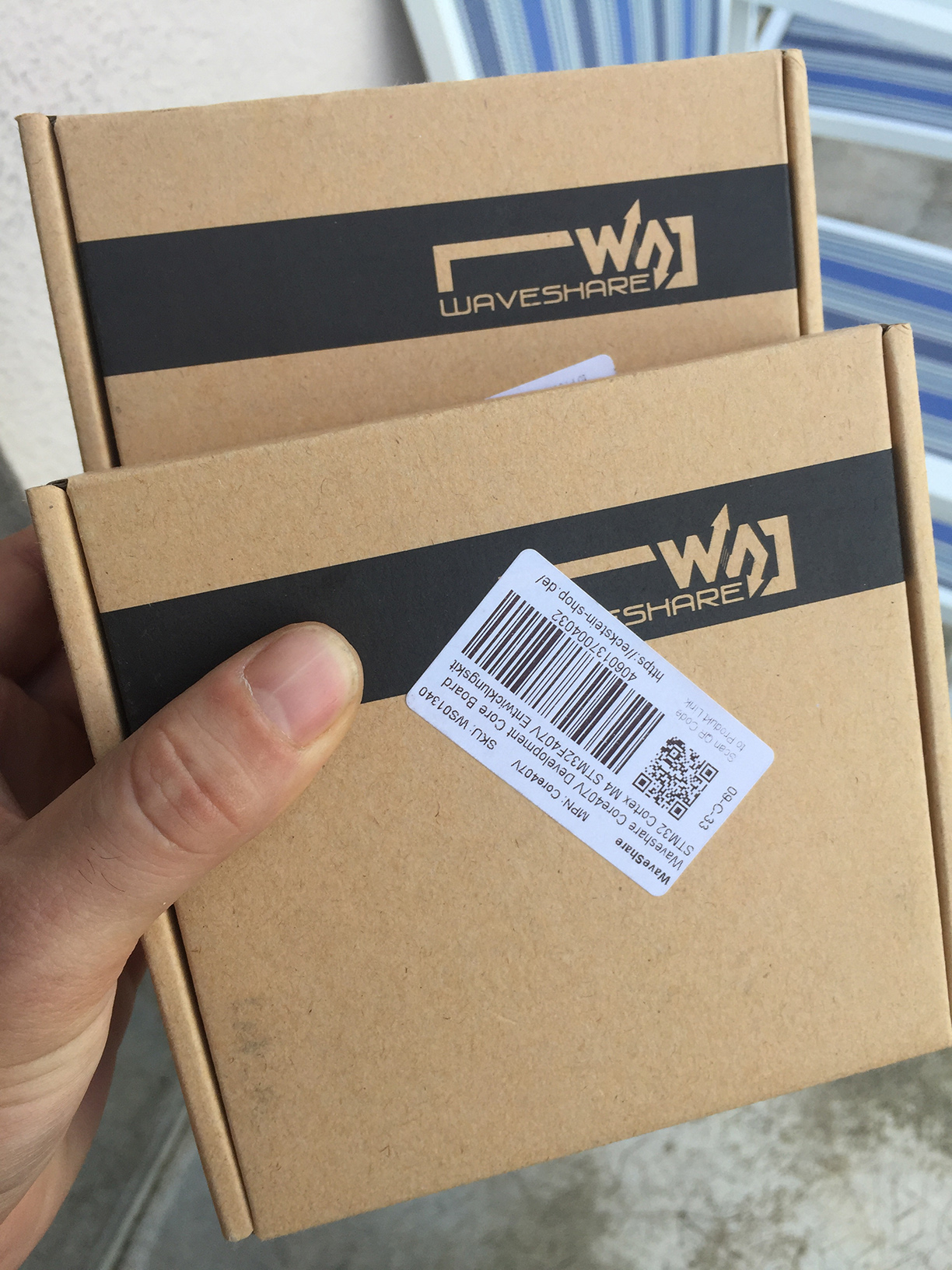
Even the box is a solid thing!
-
I think this can help too. See intouch() and getbit() functions, this is the mechanism I was talking about. Best regards
-
You can directly use the MIOS32_BOARD_J5 or MIOS32_BOARD_J10 functions as digital I/O http://www.ucapps.de/mios32_c.html tutorial #4 and #5 List of MIOS32_BOARD functions You can emulate your 16 clocks at the requested speed on an Output pin and get the state of 2 others Input pins on each clock transition you make. best
-
Hi Marco, J16 is a SPI port and you use its routine but... Your peripheral seems to communicate by an I2C bus. Its data line is a bidirectional one and there's no Chip Select, then better to use J4A for your first TT229 and J4B for the second. Or you can create your own driver by using any GPIO... Best
-
Yes. It's pretty the same method no matter of IDE version. - Install and activate it, it's free. - Choose a place for Workspace. - Create a LPCXpresso C Project. (instead of FreeRTOS Project), You just need a blank Project and selecting the good Target. - Choose the right Target, LPC1769. - Go to Program Window, Select your Blank project, Select your available interface(LPC-Link) - In the Programming window, browse and select the file \mios32_bootloader_v1_018\MBHP_CORE_LPC1769\project.bin by putting *(any) in the extension combo box filter. - Put 0(zero) in Base address if it's not already the case. - OK > Done! Best Bruno
-
Hello, YES no problem! With both interfaces. LPC-Link v1.1 and LPC-Link 2. Best
-
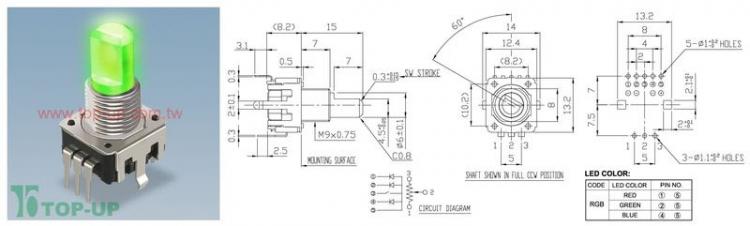
Hello, I've got a quotation for 100 pieces of 12PLRGBSD1VBF-D-15F-2B10K-001-6H from TOP-UP It's a linear 10K Potentiometer with RGB Led Shaft and Push-Switch of 0.3mm travel. Price is 3.90$ each. 100 pieces is a minimum and this is not very big. I haven't got shipment price for the moment. Specifications: The shaft type: Flatten(F) shaft length: 15mm Taper: Linear(2B) resistance value: 10K Drawing(pdf) / Specs(pdf) / Taper(pdf) Who wants some?
-
I forgot more important things I found. - The Absolute Rating Voltage is +/-5V, tried and fried ;) - CV inputs are in a 0 to 5V range. - All audio inputs are bipolar and support OverVoltage. A good hard clipping. - LoG Cut-Off CV has inverted input. Means Cut Frequency is low at 5V, High at 0V. This one must be inverted too. The Configuration Modes now: - Remember, I want the switching between the configuration modes digitally controllable. (MIDI, Recall…You know why ;) I try all the valid configurations, and finally choose the 4 most interesting. Mode 0 - PRE, VCA before VCF Mode 3 - POST, VCA after VCF Mode 1 - PAR, VCA Parallel VCF They share same Input and Output. Mode 2 - SUM, VCA + VCF, They share only output. VCF direct input is tied to ground. For this purpose I use 3x DG413 Analog Switch on the breadboard. I reduced it to 1x DG333 and 1x DG413 on PCB. All Audio purpose active components like OpAmps and Analog Switches are connected to +/-12V. We wants 2069 distortion only! The 2069 is supplied by +/-5V, then it will be the first to saturate. This is the block diagram of the switching circuit Here the circuit is in default state. The 2P/4P switch has its own line control. The two Bypass SPST form a SPDT Switch and have their own control line too. All others 5 switches are for Mode purpose. 5 is too much lines, remember I've got only 4 modes then I may reduce it to 2bits, 2 coding lines. I inserted the Switches in the circuit to get this truth table: As you can see E=B and D=C then it's reduced to 3 lines. Now I add my 2 required inputs lines, ModeA and ModeB We can extract that: It's ok, I need 1x OR gate and 1x AND gate, on PCB I use 2 small 74HC1G32 and 74HC1G08. And finally I obtain to control everything with 4 lines: 1 logic line for Bypassing, Active at High. 1 logic line for 2P/4P switching, 4P at Low, 2P at High. 2 logic lines to code the 4 Configuration Modes. Obviously you're not obliged to use this switching circuit. All I/O are individually accessible on pin header. You can use it to access I/O or to set it in the static configuration of your choice. To be continued…
-
... Precious information found once prototyped. The SIG1 and SIG2 has inverted signal audio inputs. It seems all VCA cells invert the signal, then same thing for the VCA part. ? It will need some OP AMP, this is sure now… Two Inverter OpAmp, one for each SIG input. One for the VCA We can observe in DW-8000 and DSS-1 Service manual that the VCA output has already an Inverter OpAmp Stage. I did the same, I suppose original circuity respects the internal output Impedance. LOG CV Input of the VCA seems unusable. I've got only some NJM2069BD for spare then I used the D version present in my EX-800 to test Log CV of the VCA in the 2 versions, and it appears to be definitively not usable for both! Maybe some other version (AD, DA…) of the chip release this function. I don't know. ? But I respected and reproduced the two different existing circuit. This pin is to ground in DW-8000(AD)/EX-800(D) and acts as a kind of bias(?) in a DSS-1(BD). Choices made during prototyping. - SPDT function added to the VCF outputs to switch between -12dB and -24dB… Of course. - SPDT for ByPass function… Of course too!. - Polarized caps to all audio inputs of the module, SIG1, SIG2, EXT(named like that to be clear) and 1 polarized cap on the output. I checked, with some low offset Op Amps like NE5532 or NJM4580, this is enough to maintain offset and stability in all the circuit. Then no need of big and expensive bipolar caps between stages in circuit. - Remember, I want the switching between the configuration modes digitally controllable. (MIDI, Recall…You know why ;) I try all the valid configurations, and finally choose the 4 most interesting. ...
-
Ohh! they finally reinstated the first one then this is another test:
-
It's just a Yocto pattern at the input (THX @Shuriken) and I just play on the breadboard trimmers(CV inputs), with a screwdriver ;) Please take care of your ears and speakers, it's very loud during self resonance at low and high frequencies, I push it in its limit. ... Grrrrr... Stupid algorithm on soundcloud removed my track for copyright reason!? I upload it 2 times :/. This is it:
-
Tell me. I will continue it a few today.
-
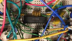
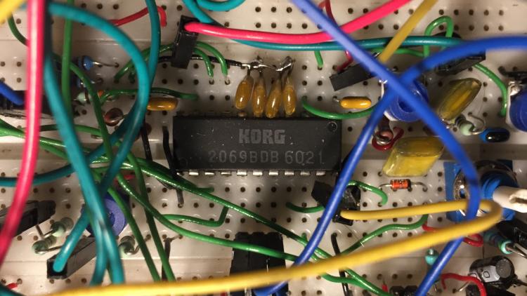
From the album: MIDIBox 2069
NJM2069 in a cable jungle! -
Now let's prototype it! I used Poly-800 Service Manual page 6: In the Poly and EX-800 the 2069 is in PRE configuration. It means the VCA is before the VCF. The VCF has 3 Voltage controlled inputs, SIG1, SIG2 and VCF In. Two VCO on SIG1 and SIG2 and a noise circuit is applied to the VCA In. The VCF 4 Poles output is the Output of the filter stage. The DW-8000 Service Manual page 22: The DW-8000 is in POST config. The VCA is after the VCF Two VCO come to SIG1 and SIG2. The Noise Circuit is directly applied to VCF In. The VCA Input connected to the VCF 4 poles output. The VCA Output is the output of the filter stage. The DSS-1 Service Manual page 18: The DSS-1 is in POST config too. The only difference is the 2 switching Op Amp added between the VCF Ouputs 2P/4P and the VCA In. Specifications - Digital and Analog control for all CV, both at the same time. - Configuration modes are controllable. - Power supply is +/-12V. - Can be use in a desktop synth or in a Modular system. After some schematic sketching this is the wild version. To be continued…