Search the Community
Showing results for 'STM32F4'.
-
I would like to have two clock outputs from my SEQ V4 to sync two delay/echo effect pedals to the sequencer. The effect pedals have a tap tempo, and I wonder if anybody think/know if this is possible. If I understand correctly the STM32F4 core can have 8 clock outputs. Are these suitable for this purpose? Is it just a normal DOUT circuit?
-
hi forum, as the stm32f4 board landed in my seqv4 it is put to use using the QUAD_IIC module connected to J4A as well. BUT i get serious dropouts hwne using the ports on the QUAD_IIC. is that a known bug or error - or is it me :-) ? cheers and thanks
-
by compiling this code: note2light-withoutDMX.zip i got errors see below...
-
I have assembled my SeqV4 modules (mbhp_core_stm32f4, wilba control surface, 2x MIDI I/O, Quad IIc R2, AOUT_NG R1, DOUT R5, PCBs from SmashTV). The STM32F4DISCOVERY board seems to work fine, no problem with the bootloader and I have successfully uploaded MIDIbox SEQ V4.088 via MIOS Studio. After connecting the STM32F4DISCOVERY board with the MBHP Core the LCDs and the SD card work as expected. Troubles begin as soon as I try to connect other modules (wilba control surface, MIDI I/O, Quad IIc tested, wilba/MBSEQ_HW.V4 on SD card root): Wilba control surface (J8/9): I get the LCD message asking to create a new session, but the core does not react to the control surface. No LED response on the surface (L31 is mounted in reverse). MIDI I/O (J11E): No response to MIDI in/output, if I start the sequencer in MIOS Studio I get timeout error messages: [MIOS32_MIDI_Receive_Handler] Timeout on port 0x20 [MIOS32_MIDI_Receive_Handler] Timeout on port 0x21 Quad IIc: The core does not boot (no LEDs on, no MIDI ports at computer) It is also strange that the CPU always runs at ~ 230% (obtained by sending the "system" command from MIOS Studio). And I have the impression that the whole board gets rather hot (I have no comparisons though). I have tried different ribbon cable orientation (very confusing for newbe), but the effect was the same. So I concluded that I have messed up the MPHP core and resoldered suspicious looking joints (having messed up 4 modules is quite possible but less likely). In particular I have tried to remove a suspected short at the left pins (see attached image) of the SD card connectors. I am also not sure, if they should be soldered to the PCB or not). The only effect was that LCDs stopped working when I connected the control surface. Searching for tests I found the troubleshooting apps in the mios32 source code. After a few adjustments I am stuck at (I am on 4.0.4-2-ARCH Linux, MIOS Studio compiled without problems): Creating object file for check.c check.c: In function 'CHECK_Pins': check.c:160:34: error: 'GPIO_Mode_IPU' undeclared (first use in this function) GPIO_InitStructure.GPIO_Mode = GPIO_Mode_IPU; ^ check.c:160:34: note: each undeclared identifier is reported only once for each function it appears in check.c:180:36: error: 'GPIO_Mode_Out_PP' undeclared (first use in this function) GPIO_InitStructure.GPIO_Mode = GPIO_Mode_Out_PP; ^ check.c:229:36: error: 'GPIO_Mode_IPD' undeclared (first use in this function) GPIO_InitStructure.GPIO_Mode = GPIO_Mode_IPD; ^ /home/ch/src/mios32/trunk/include/makefile/common.mk:160: recipe for target 'project_build/check.o' failed make: *** [project_build/check.o] Error 1 Indeed GPIO_Mode_IPU, GPIO_Mode_Out_PP and GPIO_Mode_IPD are defined in drivers/STM32F10x/v3.3.0/STM32F10x_StdPeriph_Driver/inc/stm32f10x_gpio.h, but not in drivers/STM32F4xx/v1.1.0/STM32F4xx_StdPeriph_Driver/inc/stm32f4xx_gpio.h. Sorry for the massive amount of probably unrelated details. I am pretty much stuck at the moment and would appreciate any sort of help. I am attaching images of the (i) MBHP solder joints, (ii) SD card joints, (iii+iv) two ribbon cable connections, I would consider (iii) to be correct but most images I have seen would point to (iv). Best, Christoph
-
In the beginning of this year I decided I was going to finally build The Sequencer. I built my first MIDIbox project 4 years ago, a stereo MB SID, and have been hooked since. Next to my kids, this is the greatest thing in my life, I love it. There's so many great tutorials and tips on the forum about building the SEQ V4, so there's not really a need for another one, but I thought I'd share a few things I did in my build. I used the STM32F4 based Core, with the now available PCB. To save some space in the case, I moved and removed some parts. Removed the jack and the button caps. Cut the buttons and some pins. Moved some pins to the underside. I used the Kyocera LCD's, and read a tip by Altitude about the back light. I omitted the transistor and the resistors, put in a bridge and a multiturn trim pot. Like sometimes at Mouser, the part doesn't look like the picture, but it sort of fits ;) I wanted the max MIDI OUT's, so I used 2xMIDI I/O and 2xQuad IIC boards for 12 OUT and 4 IN The PICs on the second Quad IIC board needs a modified firmware. Tim AKA "Not Mike" AKA SmashTV has it now, but if you want to burn it yourself, it's downloadable further down. The rest of the build is pretty standard. Wilba PCB, Schaeffer front panel and common parts. The case is laser cut acrylic done locally. With the mods on the Core, it's only 4 cm. high :smile: While I was at it, I built the BLM 16x4 and TPD as well (FPD file further down) The last piece was the tinted windows on the TPD, and they really look great I think I am very happy with it, and it's so much fun to play. Thank you TK for everything. Thank you Wilba for the PCB ++ Thank you SmashTV for your shop and service ++ Thank you ilmenator for the BLM and TPD, and the "bling" and of course thanks to the rest of you for all the help, support and inspiration. Beers all around edit: I thought I could buy you all beers, but it's only TK that has a working link Wilbas redirects to a Rick Astley video :), and the others don't have one oh well Cheers Hal iic_hack.hex TPD+BLM_19.fpd
-
From the album: eptheca
-
From the album: eptheca
-
I have a hard time accesing the sd card via MIOS. Does access to the SD card work via MIOS studio when only the coreboard and STM32F4Discovery and SDcard are connected? All pins are connected ok. 9 NC 1 PB2 2 PA7 3 GND 4 VDD 3v 5 PA5 6 GND 7 PA6 8 NC SD cards Shield connected to GND When connected to micro usb LD1 is blinking. When ejecting or inserting the SD card nothing hapens. 3 v is available on pin 4 and 2 data lines The correct IC's in the sockets, the resistor network connect with common pin on 1. After flashing the seq4 app should some jumpers be removed?
-
Hello I want to finish my mbseq V4 with the new core STM32F4 i m not sure that i need 4 midi input so i wanted to know if i could used the quad IIC midi board with the STM32F4 for have 2 input midi and 6 midi output and the BLM output (2 input and 2 output midi come from midi I/O board for STM32F4) Zephyrin
-
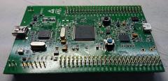
I have an STM32F4 that refuses to work with both SD & ENC28J60 ethernet modules using MIDIbox NG & CV V2. Working: Ethernet and no SD When I boot it without an SD inserted, the ethernet works fine: Ethernet cable connected: yes Ethernet MAC address: 00:39:36:30:39:31 Ethernet services running: yes DHCP: enabled IP address: 192.168.0.100 Netmask: 255.255.255.0 Default Router (Gateway): 192.168.0.1 Not Working: SD and ethernet together (ethernet gets disabled) However, the moment I insert an SD card, I get various errors and the ethernet disconnects: [MIOS32_ENC28J60_PackageReceive] glitch detected - Ptr: ff09, Status: 7fb8 (max: 05ee) cd7f or [MIOS32_ENC28J60_PackageReceive] glitch detected - Ptr: ffff, Status: ffff (max: 05ee) ffff Working: SD and no ethernet If I boot with the SD card inserted, the MAC address is recognized but the plugged-in ethernet cable isn't detected (which could be due to another error): Ethernet cable connected: no Ethernet MAC address: 00:39:36:30:39:31 Ethernet services running: no DHCP: enabled IP address: not available yet Netmask: not available yet Default Router (Gateway): not available yet When this happens, my router actually recognizes the ENC28J60 and assigns it an IP address. Here's my cheap-o eBay ethernet adapter:
-
Hello there im wondering why the stm core uses the small usb connector...i really like the normal USB connector on the LPC core this is more solid and im somewhat scared to break off the small connector on the STM32F4 core....has anybody got a solution for this ? cheers, electro
-
I'm going to now try and get my feet wet with a bit of programming, I admit that I don't know what I'm doing yet but I want to learn. What I'm trying to do is compile a build of the MB909 firmware of the STM32F4 core. I "think" I have set everything up correctly according to the wiki article and I can build the 001_forwarding_midi tutorial successfully. I'm getting an error when I make the project file. Can anyone advise me what is wrong and how I fix it? This is what Terminal is spitting out. Creating object file for app.c Creating object file for tasks.c Creating object file for seq_hwcfg.c Creating object file for seq_ui.c core/seq_ui.c: In function 'SEQ_UI_LCD_Update': core/seq_ui.c:2664:11: warning: variable 'animation_r_ptr' set but not used [-Wunused-but-set-variable] core/seq_ui.c:2663:11: warning: variable 'animation_l_ptr' set but not used [-Wunused-but-set-variable] core/seq_ui.c: At top level: core/seq_ui.c:800:12: warning: 'SEQ_UI_Button_MultiCopy' defined but not used [-Wunused-function] core/seq_ui.c:892:12: warning: 'SEQ_UI_Button_MultiPaste' defined but not used [-Wunused-function] Creating object file for seq_ui_todo.c Creating object file for seq_ui_menu.c Creating object file for seq_ui_bookmarks.c Creating object file for seq_ui_edit.c Creating object file for seq_ui_lcd.c Creating object file for seq_ui_mute.c Creating object file for seq_ui_pmute.c Creating object file for seq_ui_pattern.c Creating object file for seq_ui_pattern_remix.c Creating object file for seq_ui_song.c Creating object file for seq_ui_trkevnt.c Creating object file for seq_ui_trkmode.c Creating object file for seq_ui_trkdir.c core/seq_ui_trkdir.c: In function 'LCD_Handler': core/seq_ui_trkdir.c:274:7: warning: unused variable 'i' [-Wunused-variable] core/seq_ui_trkdir.c:265:14: warning: unused variable 'dir_names' [-Wunused-variable] Creating object file for seq_ui_trkdiv.c Creating object file for seq_ui_trklen.c Creating object file for seq_ui_trktran.c Creating object file for seq_ui_trkgrv.c Creating object file for seq_ui_trkmorph.c Creating object file for seq_ui_trkrnd.c Creating object file for seq_ui_trkeuclid.c Creating object file for seq_ui_trkrec.c Creating object file for seq_ui_trgasg.c Creating object file for seq_ui_fx.c Creating object file for seq_ui_fx_echo.c Creating object file for seq_ui_fx_humanize.c Creating object file for seq_ui_fx_limit.c Creating object file for seq_ui_fx_lfo.c Creating object file for seq_ui_fx_scale.c Creating object file for seq_ui_manual.c Creating object file for seq_ui_util.c Creating object file for seq_ui_bpm.c Creating object file for seq_ui_bpm_presets.c Creating object file for seq_ui_opt.c Creating object file for seq_ui_save.c Creating object file for seq_ui_midi.c Creating object file for seq_ui_sysex.c core/seq_ui_sysex.c: In function 'Button_Handler': core/seq_ui_sysex.c:194:6: error: too few arguments to function 'FILE_SendSyxDump' In file included from core/seq_ui_sysex.c:25:0: /Users/rowanspicer/svn/mios32/trunk/modules/file/file.h:130:12: note: declared here make: *** [project_build/core/seq_ui_sysex.o] Error 1
-
 So after four years today I finally bit the bullet and ordered a SEQ CS PCB and a LPC17 core board. I started doubting this decision soon after as I bumped into something only mystically refered as "the future MIDIbox SEQ V4 Plus firmware", which apparently requires the newer STM32F4 board to function. I guess I could still try to change my order to get the STM32F4 board instead, but here's what's on the top of my mind: Is it worth it? When will it be available? Where can I find more info? Constructing a MBSEQ with the LPC17 board seems so much easier because it seems to have all the needed connections on the board itself. If I decide to go with the STM32F4 board, what boards do I need for external connectors? MBHP_ETH goes for ethernet, MIDI I/O modules for MIDI ins and outs, but what for USB and SD card slot? What about the CV/Gates port? Is it really needed if I don't have analog gear? What's the difference with MIDI I/O board and quad IIc_MIDI board? Can I install a BLM without the IIc_MIDI board? After I acquire all the needed boards; am I able to cram them all inside the case? I'll be using the acrylic case designed by smokestacksproductions. I read somewhere that fitting everything in a Heidenreich case is a bit tricky. I'd like to hear also some tips on how to attach the boards on the bottom part of the case. I've seen some pictures with hot glue and spacers. If anyone has build a MBSEQ with these hardware specs, I'd be happy to hear about your solutions and to see pictures of the insides. Any answers are appreciated. Thanks!
 -
Hello there in the past ive always uploaded the hex with midi,...but i notice it does not work with the new stm32F4 core. Also after uploading the bootloader with the stm software...it does not show up in the mios midi terminal. whats have i done wrong? cheers, Vincent
-
Hello everyone. I want to connect another DIN & DOUT chain on mbhp core stm32f4. It is possible to drive J19 to work as J8/9?? Best Regards, Tilemachos
-
From the album: Uploads
-
Hey, I'm experiencing something odd - if I call EEPROM_Init(0) in APP_Init then I cannot upload code using the bootloader unless I reset the board and hold the user (blue) button. Has anyone else experienced this? I'm guessing this has to do with EEPROM_Init touching the flash and somehow messing it for the bootloader... Thanks :)
-
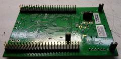
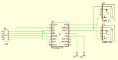
Hi there, need some hints for my project (midification of a tube preamp): I try to get output of an PGA2311, but no success so far. The PGA2311 is connected to the Core via J19, RC1 is used. Extra +/-5.0 Volts for the analogue section is provided via extra power supply. Here is my code: For Initialization: For change of Gain: Initialization returns "000" and Change of Gain return "255" in the Debug Window of MIOS Studio which is well expected from my side. Maybe someone can help me? Kindly :santa: :santa: mwpost
-
I came across this today https://github.com/MrBlueXav/Dekrispator I've loaded it on to a STM32F4 and it actually sounds rather good. Has anyone else tried this out? I can imagine a very cool cheap synth based on this code.
-
I may have messed up my STM32F4 board. I accidentally plugged the 74HCT541 in backwards while trying to power it up for the first time. No lights came on. I replaced both chips on the core module and got the boot loader and LCD working. I installed Midibox NG 1.032 but my SD card fails. :( From MIOS Studio 2.4.6 (here are the details) [319531.507] sdcard [319531.499] SD Card Informations [319531.500] ==================== [319531.500] ERROR: Reading CID failed with status -256! [319531.500] ERROR: Reading CSD failed with status -256! [319531.500] [319531.500] Reading Root Directory [319531.500] ====================== [319531.500] SD Card: not connected [319531.500] Failed to open root directory - error status: 12 [319531.500] done. I tried two 8 gig sd cards (one Ultra) format FAT 32. ========================== I checked continuity between the solder pads of the sd card before assembly nothing seemed to be causing a short circuit. Is there a way to trouble shoot SDCard or Connector and the STM32F4 board ? I couldn't locate error status codes while searching the forum. Thanks, A confused GuitarNut
-
Hey, i soldered the PCB for the STM32F4 Core Module and tried now to get the LCD Module working... I bought the Displaytech LCD 162a, and wired it like in the LCD-Module Tutorial. After that, i loaded the LCD-Tutorial Code on the Core, where it should print out the systemtime while the LED is modulated by a PWM..the led modulation works, but all i see on the lcd are 16 black bars... I have seen, that some other users had the same problem, but not with a 2x16 character display... I double-checked the soldered pins, and they look fine Anyone got some advices ? thanks
-
Hi All, I've got an stm32F4 and a speakjet chip knocking around, so I thought I'd try out the speakjet synth for mios32 in mios32\trunk\apps\synthesizers\midibox_sj_v2. . Unfortunately, the schematic in the svn repo for the app. is for the lpc core module, looking at the schematic compared to the lpc module pinout, if I've got this right, the speakjet chip connects d2,m0,m1,rst to J10.d3, .d2, d1 and .d0 and the speakjet rcx pin connects to J5b.A7, will the midibox_sj2_v2 app. work if I connect the respective pins as they're laid out on an stm32F4 (pe8,9,10,11 for the J10 pins and pb1 for the j5b.a7-rcx connection)?
-
Hello, I got my STM32F4 board today, and for reasons beyond my understanding I cannot get any LEDs other than LED1 to light up. I am modifying the application template - so my code is as minimalistic as it gets. If I call MIOS32_BOARD_LED_Set(1,1), the green LED turns on. MIOS32_BOARD_LED_Set(2,1) or even MIOS32_BOARD_LED_Set(0xF, 1) do nothing. Some answers to potentially obvious questions: 1) I am certain I am properly recompiling the code and uploading, as I see the green led no longer lighting up when trying MIOS32_BOARD_LED_Set(2, 1) and lighting up again when I switch to MIOS32_BOARD_LED_Set(0xF, 1). 2) I tried commenting out the code in the timer function and simply turning the LEDs on in APP_Init() 3) I am compiling using the following env variables: export PATH=$PATH:/Users/eran/Projects/mutebox/gcc-arm-none-eabi-4_7-2013q3/bin export MIOS32_PATH=/Users/eran/Projects/mutebox/mios32-svn export MIOS32_BIN_PATH=$MIOS_PATH/bin export MIOS32_GCC_PREFIX=arm-none-eabi export MIOS32_FAMILY=STM32F4xx export MIOS32_PROCESSOR=STM32F407VG export MIOS32_BOARD=MBHP_CORE_STM32F4 export MIOS32_LCD=universal What am I missing? Thanks!
-
Hallo zusammen, ich stehe mal wieder auf dem Schlauch. Möchte gerne meinen DIY-Tube-Preamp midifizieren. In einem ersten Schritt soll für einen Prototypen der Volume-Poti verschwinden und eine Lautstärkeregelung über das PGA2311 erfolgen. Es hapert im Moment an der Verdrahtung von diesem IC mit dem STM32F4. Hat jemand einen Schaltplan hierfür?? Mwpost