Search the Community
Showing results for 'STM32F4'.
-
Hi all! I like to control my Seq V4 (LPC1769) with my MidiboxNG (STM32F4) via Midi. Is it correct if i connect LPC1769 Core P2.1 to STM32F4 Core PA2 and LPC1769 Core P2.0 to STM32F4 Core PA3? Thanks for your advice. Marxon
-
Hi everybody! I'm thinking about building a hybrid synth with the new STM32F4 core. With hybrid, I mean something like the Mutable Instruments Ambika: Digital Oscillators and modulators (envelopes, lfos) but analog filters. I'm thinking about an 8-voice synthesizer with 3 envelopes, 3 lfos, 3 oscillators + noise per voice. Now I'm wondering how powerfull the new STM32F4 core really is. If I wanted to run a total of 24 wavetable-oscillators, 24 envelopes, 24 lfos, and additional things like ringmodulators, noise, ... on it with a samplerate of at least 44.1kHz, would it manage the load? As a comparison: The Ambika uses a separate ATmega@20MHz for each voice. Its signal processing is lofi with mostly 8bits resolution, but some stuff is done at 12 or 16bit. A voice on the Ambika has 2 oscillators, 2 envelopes, 2 lfos and runs at 39kHz (if I read it right). So if I take that as a guide and scale it up - I would need at least 160MHz to run 8 voices in parallel. The DMA of the STM32 makes transferring data a bit lighter and the 32bit architecture makes calculations with 16bits an easy thing. So it could even fit a third oscillator per voice... I know, the comparism to the 8bit ATMega is rubbish. But at least it could give an idea of the workload that comes with such a synthesizer design. I find it really hard to even estimate the power of the STM32F4. what do you think?
-
Hi - I was about to order parts to put together an MBSeqv4 when I noticed that there is a core stm32f4 module available. Is this now the preferred core to use with seqv4 or is it still the LPC17 (which seems more expensive, and seems to now feature a mismatched pin config...)? I've looked through Ucapps and this forum and was left feeling unsure.
-
I have a MBCV V2, and a NG I use W7 When connecting them to my computer, they both come up in the Device Manager as MIDIbox CV and MIDIbox NG but in Send SX and Ableton Live, only one come up I have used the Bootloader Update app. to "set single_usb 1" and "set device_id" Still it's not working Any suggestions?
-
I have upgraded my MB64 for my AY-synth to NG on a STM32F4 to take advantage of the "Radio buttons" DINx2 (15 buttons) DOUTx2 (15 LED's) 2 pots Q: Is it possible to connect the 2 pots directly to the STM32F4? Q: Are the MIDI notes coming in through USB, merged with the CC messages from the buttons and output to MIDI1 OUT on PA2? Best regards Halvor
-
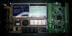
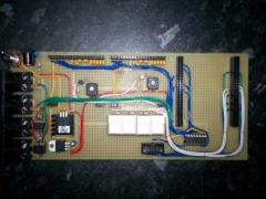
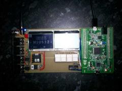
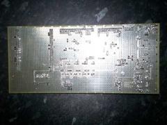
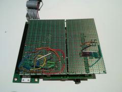
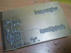
various photos from my STM32F4-Boards
-
-
-
which supported DAC for simple Audio-Sinus (Stereo/dualchannel) generation? (80-4000Hz) Also need 3DAC Channel for LFO (20-4Hz) Sinus for 3x LED-Stripes (660nmRed.Blue,..) which are for spa-like Skin penetration... that is the main purpose of the thing. 1DAC Channel for LFO Sinus generation for bodyshaker. (20Hz-60Hz) so stm32F4 + 2 Channel Audio DAC 4 Channel LFO DAC. any idia for DACs hardware?
-
 Hi, Been a MIDIbox user for a few years now (thanks, TK!) but this is the first time I've not found my question already answered somewhere. Having been on MIOS8 for so long, I recently got an STM32F4 Discovery to start work on replacing my existing board. It was all going really well until I tried add an RTOS task with (I presume) not enough stack memory allocated, resulting in a "hard fault at PC=0x00000000". I've amended my code to allocate a bigger stack, but now I seem to have no way to upload any more. The error condition occurs very soon after bootup (in App_Init()), but using the reset button on the Discovery board doesn't seem to trigger an upload request - MIOS Studio doesn't respond in any case. I'm guessing my config must have fastboot turned on. I found a mention of the "BSL Hold" jumper here http://www.ucapps.de/mios32_bootstrap_newbies.html, but that seems to be for the LPC17 board only. Is there any equivalent on the Discovery?? Hoping someone can help! Regards, - Paul
 -
i uploadet "$MIOS32_PATH/apps/misc/usb_mass_storage_device" on a core stm32f4... the lcd says "sd connected"... but it is not shown as device in browser nor diskmanager (where you see all mounted or not mounted partitions...) is there a driver needet? (maybe only mac tested?)
-
-
From the album: eptheca
-
From the album: eptheca
-
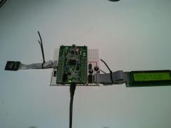
Hi, unfortunately i have some two problems with my new STM32F4 core module. I uploaded the actual bootloader 1.015 and Midibox NG 1.029 version. This ports are wired J16, J8/9, J19, J15A and J15_S. Problem 1: The event Event Pool Allocation is 24480 of 24576 bytes (99%) exactly like using the LPC1769 core. Shouldn't be there more bytes available :question: Problem 2: The LCD does not work (backlight and contrast are ok). It is a 2x16 HD44780 display. I have triple checked the wiring and soldering. TK, your help is needed :) Best regards Marxon
-
From the album: Marxon's M³ - MarxonMixvibesMidibox
-
From the album: Marxon's M³ - MarxonMixvibesMidibox
-
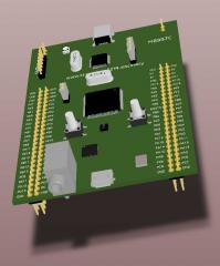
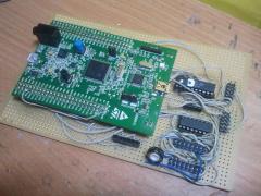
Im planning a prototype of the stm32f4-core using the stm32f4discovery. unfortunately i cant find any notes on J28. nothing in the diagram and nothing in the mios32-include-files either.... basically i want to connect two ks0108 lcd-displays, which will need 4 cs-signals. on the lpc17-core they are provided via J28, but theres nothing like that on the stm32f4-core. am i missing something or is this just not implemented (yet) ?? mOnO
-
Hi, I'm building a MCU type controller and I'm starting to design some PCB's for the various modules. I'm planning to share them here so other users can use them if they want, if that's ok. The first and simplest one is an 8xOLED carrier board to connect to J15A of the STM32F4 core. Initial tests on a breadboard with 2 screens work fine. It is my first time using Kicad and also designing a 2-layer board, so I'd like to get some feedback before sending them to the fab house. OLED's are 0.96'' SSD1306 4-wire SPI type Mechanically the OLED's are plugged into 1x7 sockets Each 'channel' is exactly 1.1 inch wide. It leaves a little wiggle room between the screens, and should allow the case too be quite compact I remember seeing another schematic with added 100nF decoupling caps, but they're not on Thorsten wiring diagram, so I'm wondering if I should add those NOTE: I'm going to extend the board to avoid having the holes running under the OLED's.
-
Looking at the core schematic, I see CS7 is connected to both Q7 of the 74HC595 and PD7 of the STM32F4, whereas CS0-CS6 are connected only to Q0-Q6 of the 74HC595. If PD7 is also an output pin, I wonder if PD7/Q7 could be interfering with eachother ?
-
wiki well lets try... I saw on the LPC17 shematic: That on J5A - A3 a DAC is aviable @ I assume 0-3.3V? for CV I need a level shifter to get 0-5V (Analog) >>> I assume OP-AMP will do the job I will use some pins from the DIO-MATRIX as GATES, so i need no Logical Level-Shift - (0V and 5V) Most of UI and the GATES is done by DIO-Matrix: Features (very minimalistic) a ADR and a midiclock-synced-LFO mixed to one CV-Output, 5 Real Encoders (4 Menue Encoders, 1 Menue-Encoder to cycle thru the Pages) 4 Virtuel Encoders on 4 Menu-Pages (= 16 V-Encoders), 4 LEDs to indicate Menue-pages, 4 Encoders / 2 Displays SHOW ing / DO ing: Page 0: ENVELOPE ENCODER 0.A / 10 Switch = curve type 1.D / 11 Switch = curve type 2.R / 12 Switch = curve type 3.+-/ 13 Switch = long/short time Display 1: Scope: ADR - Curve Display 2: Scope: Mixed real CV ADR+LFO Page 1: LFO ENCODER 0.Rate / 10 Switch = ... 1.Wave / 11 Switch = ... 2.x/4 / 12 Switch = ... 3.+- / 13 Switch = ... Display 1: Scope: LFO - Curve Display 2: Scope: Mixed real CV ADR+LFO PAGE 2 MOTION SEQUENCER ENCODER 0.LENGTH / 10 Switch = Activate Motionsequencer 1. / 11 Switch = 2.x/4 / 12 Switch = 3.BPM / 13 Switch = Activate internal MidiClock Display 1: MSQ-Length-Progress Bar + Length in Steps Display 2: Tact System BPM and MasterLoop Progress-Bar Page 3: DISK ENCODER 0.Load Preset Nr / 10 Switch = DO 1.Save Preset Nr / 11 Switch = DO 2.Letter / 12 Switch = Small-Big-Letter 3.Cursor-Position/ 13 Switch = clear Name Display 1: Preset NR Display 2: Preset Name Page 4: SYSTEM ENCODER 0.set MidiCH / 10 Switch = single Channel/all Channels 1.set CV-Trigger-Note / 11 Switch = single note/all notes (automatic assigned to Gate 1) 2.set Gate2-Trigger-Note / 12 Switch = single note/all notes 3.set Gate3-Trigger-Note / 13 Switch = single note/all notes Display 1: Midi Monitor - showing Notes-Nr. and MidiChannel Display 2: Midi Monitor - showing Notes-Nr. and MidiChannel Panel-Layout - and in real world: the case is also "very" diy ;) see the thru Welt-point... @ the moment waiting for M1.6 Screws (a wire holds the displays at the moment)... searching for Level-Shifters.... before compiling the first code i have to set my environment variables from STM32F4: PATH="/home/inet-stick/midibox/gcc-arm-none-eabi/bin:/usr/local/sbin:/usr/local/bin:/usr/sbin:/usr/bin:/sbin:/bin:/usr/games:/usr/local/games:/home/inet-stick/program:/home/inet-stick/Schreibtisch:/home/inet-stick/Schreibtisch/test:/snap/bin" MIOS32_PATH=~/midibox/mios32 MIOS32_BIN_PATH=$MIOS32_PATH/bin MIOS32_GCC_PREFIX=arm-none-eabi MIOS32_FAMILY=STM32F4xx MIOS32_PROCESSOR=STM32F407VG MIOS32_BOARD=MBHP_CORE_STM32F4 MIOS32_LCD=universal to LPC1769 (linux... sudo nemo.... etc/environment... restart linux... have fun doing coding....) PATH="/home/inet-stick/midibox/gcc-arm-none-eabi/bin:/usr/local/sbin:/usr/local/bin:/usr/sbin:/usr/bin:/sbin:/bin:/usr/games:/usr/local/games:/home/inet-stick/program:/home/inet-stick/Schreibtisch:/home/inet-stick/Schreibtisch/test:/snap/bin" MIOS32_PATH=~/midibox/mios32 MIOS32_BIN_PATH=$MIOS32_PATH/bin MIOS32_GCC_PREFIX=arm-none-eabi MIOS32_FAMILY=LPC17xx MIOS32_PROCESSOR=LPC1769 MIOS32_BOARD=MBHP_CORE_LPC17 MIOS32_LCD=universal (the SSD1306 is a "universal") since there was already a mios application in the FLASH, i uplodadet with MiosStudio the actual Bootloader In Mios-Studio - there is the Terminal - where i typed help, and set following: and i noticed that i mounted my G-LCDs 180° wrong... so i choose the ROTATED VARIANT, now its all right... these are all commands: set usb_name CV set lcd_type GLCD_SSD1306_ROTATED set lcd_num_x 2 et lcd_num_y 1 set lcd_width 128 set lcd_height 64 store how ever, num xy and width height will be later overwritten in the app itself....: #define APP_LCD_NUM_Y 1 #define APP_LCD_NUM_X 2 #define APP_LCD_WIDTH 128 #define APP_LCD_HEIGHT 64 #define APP_LCD_LINE_OFFSET 0 #define APP_LCD_COLOUR_DEPTH 1
-
-

LoopA V2 Introduction, Features & Support Thread
latigid on replied to Hawkeye's topic in MIDIbox User Projects
Were the CN3 jumpers removed from the DISCO board? Otherwise the SWD programmer is connected to two STM32F4 chips. To my knowledge the circuit shown is correct but it has been a few years since I tried it. -
On another note, I looked at current consumptions of various OLED's, and according to this page, a 128x64 0.96” can pull 21mA at max contrast with all pixels lit. As the STM32F4 board docs state, the integrated 3.3V regulator can only supply 100mA max. I wonder if problems some people were having with multiple OLED's might be related to that. So to be on the safe side and to avoid heating the poor little SMD IC, I'm going to add an optional on-board 3.3V regulator or input.
-
"normally" we use here 7 Pin SPI SSD1306 (GND,VCC,D0,D1,RES,DC,CS) connected like this: purple Lines = CS-Lines: the first (8or?) 16 CS/purple lines you get direct from the Core STM32F4, > http://www.ucapps.de/mbhp_core_stm32f4.html the 48 Rest CS-Lines from 595-Dout-Shiftregistors-Pins (6xICs with each 8 Pins) > we call that http://www.ucapps.de/mbhp_dout.html The Update Rate will be a bit slow - but for Label a static Mixer Desk, it will be ok? custom Bitmaps: http://wiki.midibox.org/doku.php?id=how_to_create_custom_glcd_fonts_icons_bars_for_midibox_ng @ Labelitself, I myself have a simular thing, but for a Midi>CV Device, i have to label Encoders... i managed it to save a huge array of "chars" - like this...: char Label[512][8] = { {'3','0','3',' ',' ',' ',' ',' '}, {'6','0','6',' ',' ',' ',' ',' '}, {'7','0','7',' ',' ',' ',' ',' '}, {'8','0','8',' ',' ',' ',' ',' '}, {'9','0','9',' ',' ',' ',' ',' '}, {'-',' ',' ',' ',' ',' ',' ',' '}, {'*',' ',' ',' ',' ',' ',' ',' '}, {'/',' ',' ',' ',' ',' ',' ',' '}, {'+',' ',' ',' ',' ',' ',' ',' '}, {'A','M','P',' ',' ',' ',' ',' '}, {'A','M','P',' ','E','N','V',' '}, {'A','M','P',' ','L','F','O',' '}, {'A','M','P',' ','M','S','Q',' '}, {'A','D','S','R',' ',' ',' ',' '}, ... with all possible Names - that i could use for Control-Voltage Projects.... i save this on SD-Card, on a .sys file (no PC involved the microcontroller do that) - in a Patch aka Song i then Recall it like this: MIOS32_LCD_DeviceSet( 3 ); // select Display 3 MIOS32_LCD_CursorSet(0, 1); // Select Vertical the second Line, Leftmost Horizontal MIOS32_LCD_PrintFormattedString("%c%c%c%c%c%c%c%c", // 8 Chars is max if you use BIG-FONTS Label[ aout[ENC].sel_label] [0], Label[ aout[ENC].sel_label] [1], Label[ aout[ENC].sel_label] [2], Label[ aout[ENC].sel_label] [3], Label[ aout[ENC].sel_label] [4], Label[ aout[ENC].sel_label] [5], Label[ aout[ENC].sel_label] [6], Label[ aout[ENC].sel_label] [7]); where ENC is the Encoder Number where the LCD is situated. aout[].sel_label: i save that Var on SD-Card-with the Patch / and load the Patch via Midiprogramchange. // with a given Number you adress a Name... you can also custom Labels, with ease with 2 additonal Rotary Encoders (while one is the cursor) (and the other one change the Letter), you might need for a UI-for Midibox at least 3 Encoders(with inbuilt pushbuttons) and 1 SSD1306 in order to SAVE and LOAD or ADD Custom Names...
-
Hi, This does not belong directly to the MIOS, but I haven't found a better sub-forum for my question... I'm trying to learn a lot of the low level stuff associated with MIDI right now. Mostly about USB connection. The svn repo is pretty good for it. I learned a lot of it already... I'm thinking about implementing myself(for learning purposes) a MIDI-USB connection with my STM32f4 dev board. I'm planning to use an ULPI PHY for HiSpeed Connction to achieve lowest latencies(8 times lower latency than FS). I think the Interrupt transfer method should be the best fit for it, since it has guaranteed latency. But now I saw in the svn repo that the MIDI-USB endpoint descriptor uses only bulk as transfer method. Is this just for the compability issue or is it a wrong idea to use the interrupt transfer method, to achieve lowest latencies? Ah just for record, I'm a pretty fussy drummer regarding latencies, since I hear/feel a small difference between 5ms and 10ms(measured and compared by ear...). Best Regards Philipp