Search the Community
Showing results for 'STM32F4'.
-
Does anyone have spare sd card holders for the core or a suggester part substitution? (It is actually for a different pcb but is the same part as used on the stm32f4 core) 3M have stopped manufacturing them and I havent found an alternative that is the same size as SD-RSMT-2-MQ or SD-RSMT-2-MQ-WF ( I have found 9/11 pin versions which are shorter with different positions for the mounting tabs). Thanks a lot.
-
 Quite a while back I worked into the pyBLM code to get it to work with Launchpad Mini mk3s. I must confess it has sat unused for way too long, I mentioned it being ready to Borfo like 3 years ago! But I have revived the computer it was on and done some testing, it seems pretty OK so I have decided to push a fork here: https://bitbucket.org/monokinetic/pyblm Having refreshed my memory of the changes I had to make, I should note that for my fork: this is designed for Launchpad mini mk3 only because the MIDI messages changed. I don't have any mk2 to combine with my mk3s to test this. Use Borfo's original if you're running Launchpad mini mk2s. I've tweaked the code to recognise the latest MBSeqV4+ on STM32F4 core. It might not work if you use a different set up. Major props to Borfo for providing this. Without the original start I would have never been able to wrap my head around it FWIW I use it on macOS Ventura. To get the libraries to work I needed to: Install pipx. Then use it to install the dependencies listed in the README. Get macOS to use the virtual environment with: python3 -m venv ~/.local/pipx/ Activate the pipx env with: source ~/.local/pipx/bin/activate Then run the script with: python3 pyBLM.py A more experienced Pythonista might advise you otherwise, but it worked for me..... Hopefully this will enable others to enjoy the lightshow one day!
 -
 good evening everyone, after switching on my stm32f4 board, I would like to query all inputs ( DIN and AIN ) once under mios32 and send the values obtained once via midi in order to update my software ( Traktor ). Unfortunately I have no idea where I have to insert the necessary code e.g. in NG or midio128, querying buttons and pots already works so far, can someone please enlighten me, thanks for your support, greetings ranger930
 -
Hi, is this working with midibox32 and stm32F4 core ? If yes, which config files need to be configured? I need to have round about 240 outputs for low current led's. Thank you for your help. Br ranger930 Update: i found the answer !
-
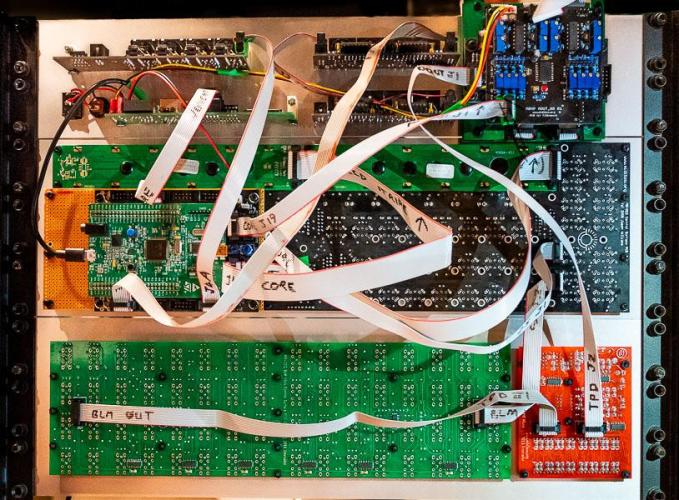
Finished my Seq V4 - Wilba CS, stm32f4 core, 2x midio out, 1x iic quad midi, 16x4 BLM, TPC, AOUT_NG, DOUT, cutom breakout board for DOUT and AOUT_NG and the Westlicht seqboard (for SD card, etthernet, +/-12V). Only issue I have is that there is up to 25mV offset on a couple of channels of the AOUT_NG, which is within spec according to the tlv5630 datasheet - I am going to make another AOUT_NG board with dual inverting output stages and a trimmable offset I think. Otherwise I am really happy with it - thanks to all the contributors !
-
hi everyone can anyone tell me if i can use this board to run mbseq v4 on it https://www.st.com/en/evaluation-tools/nucleo-h723zg.html i want to use it cause it has faster cpu then stm32f4 ,so i am hoping for more precision in midi data thank you in advance bests k
-
Heya! I was wondering if it is possible to have DIN sync clock out or even (one) CV/Trigger/Gate per sequence with the seq v4 lite. On the project page it is stated "working, but configuration is too difficult, therefore not documented." From how I understand, DIN sync can be achieved via a DOUT sihft register with 5V logic levels in the stm32f4 core. I assume the complication in the v4 lite project comes from the fact, that there is no display and thus no way to configure/set the clock/start/stop signals? Maybe someone can shed a light on how it could be achieved? I'm happy to change the software to make it work if that is necessary but would need some hints. Best regards, stahl
-
I remember that I added STM32F1 support on a "good will basis" without continuous testing, therefore it's not officially available (means: you've to try it, and if it doesn't work anymore, roll back to a working version) Limitations: only 24k instead of 64k configuration memory (.NGC file) .NGR files are directly processed from SD Card and not from RAM, which means that such scripts are much slower - however, as long as NGR files are not processed by your use case, or only sporadically used, no real impact on the overall performance only 1 DIO port: // STM32F1: J5A+J5B // STM32F4: J5A+J5B, J10A, J10B // LPC17: J5A+J5B, J10, J28 only 6 (instead of 8) direct AIN inputs only 3 UART based MIDI IN/OUT (instead of 4) Best Regards, Thorsten.
-
Hei I have some SPI problems here... A AINSER slows down the SD-Card Access - so the programm is not usable anymore. I already optimized the Ainser-Side (see below), but that is not enough, I dont know if it is the prescaler Factor, that also changes SD-Card in a way (since booth are SPI...) I save a lot off informations on the SD-Card, so each percent off performance makes seconds off less waiting time. Is there something like a prescaler that can be set for the SD-Card?= How give the SD-Card more priority? I know how to give prioritys for RTOS Task that i created, but i dont know how to do that with SD-Card (on rootlevel) thx for any info! I have 2 AINSER8 moduels connected to a STM32F4(disconver), not multiplexed - i have 16 faders connected directly to them. as soon i scan the AINSER: static void TASK_AINSER_Scan(void *pvParameters){ // This task scans AINSER pins and checks for updates portTickType xLastExecutionTime; xLastExecutionTime = xTaskGetTickCount(); while( 1 ) { vTaskDelayUntil(&xLastExecutionTime, 10 / portTICK_RATE_MS); // 202 orginally 1ms // scan pins AINSER_Handler(APP_AINSER_NotifyChange); } } The Write or Read on the SD-Card goes up from 1seconds to 14seconds (in my case) so i copied the ainser.c to my project, and made some edits, the most significant emprovement was to change the prescaler from 64 to 8: // init SPI port for fast frequency access MIOS32_SPI_TransferModeInit(2, MIOS32_SPI_MODE_CLK0_PHASE0, MIOS32_SPI_PRESCALER_8); // Initialisierung des SPI-Ports i also tryd other values, but on some values the Ainser didnt react at all, or i got random values. When i remove this Prescaler LINE, the AINSER gives no output to my code, what makes me a bit wondering since in MIOS-FUNCTIONS there is statet: So my expirience - the Prescale may not have a effect on SPI2, but on SPI0 (where my SD-Card is connected). I also changed to get this Prescaler8 working, The driver from MIOS32_SPI_PIN_DRIVER_STRONG to MIOS32_SPI_PIN_DRIVER_WEAK (which is i know not recommented): // pins in push-poll mode (3.3V output voltage) MIOS32_SPI_IO_Init(2, MIOS32_SPI_PIN_DRIVER_WEAK); // 2: Ainser_SPI - J19 i then tryed to remove the Multiplexer Code, and fixed the modules to a count off 2, At the end i have 4 seconds Access Time to my SD Card which was without AINSerial 1second And without my modifications 14 seconds I already set the priority off Tasks like this: // TASK - PRIORITYS #define PRIORITY_TASK_SEQ ( tskIDLE_PRIORITY + 5 ) // higher priority than MIDI receive task! #define PRIORITY_SD ( tskIDLE_PRIORITY + 3 ) #define PRIORITY_LOPRIO ( tskIDLE_PRIORITY + 2 ) #define PRIORITY_LCD ( tskIDLE_PRIORITY + 0 ) // idle #define PRIORITY_PAD ( tskIDLE_PRIORITY + 0 ) // idle #define PRIORITY_TASK_AINSER_SCAN ( tskIDLE_PRIORITY + 0 ) // orginal this was 3 So the SD-Task (where i write things on the SD-Card with mutexes and stuff...) is already High priority > off course the SEQuencer is higher... the whole Ainser.c code then looked like this: #include <mios32.h> #include "ainser.h" #include <string.h> ///////////////////////////////////////////////////////////////////////////// // Local variables ///////////////////////////////////////////////////////////////////////////// static u8 ainser_enable_mask; static u8 ainser_muxed_mask; static u16 ain_pin_values[16]; //2 Modules 8 pins static u16 previous_ain_pin_value; const u8 pin_lookup[8] = {7,6,5,4,3,2,1,0}; ///////////////////////////////////////////////////////////////////////////// // Local Prototypes ///////////////////////////////////////////////////////////////////////////// static s32 AINSER_SetCs(u8 module, u8 value); ///////////////////////////////////////////////////////////////////////////// //! Initializes AINSER driver //! Should be called from Init() during startup ///////////////////////////////////////////////////////////////////////////// s32 AINSER_Init(u32 mode){ // pins in push-poll mode (3.3V output voltage) MIOS32_SPI_IO_Init(2, MIOS32_SPI_PIN_DRIVER_WEAK); // 2: Ainser_SPI - J19 // orginal this was MIOS32_SPI_PIN_DRIVER_STRONG MIOS32_SPI_PIN_DRIVER_WEAK // ensure that CS is deactivated AINSER_SetCs(0, 1); // CS für Module 0 AINSER_SetCs(1, 1); // CS für Module 1 // Dont use Muxes ainser_muxed_mask &= ~3; // Sets the enable mask for modules which should be scanned ainser_enable_mask |= 3; // clear all values memset(ain_pin_values, 0, sizeof(ain_pin_values)); previous_ain_pin_value = 0; return 0; } ///////////////////////////////////////////////////////////////////////////// //! This function should be periodically called to scan AIN pin changes. //! A scan of a single multiplexer selection takes ca. 50 uS on a LPC1769 with MIOS32_SPI_PRESCALER_8 ///////////////////////////////////////////////////////////////////////////// s32 AINSER_Handler(void (*_callback)(u32 module, u32 pin, u32 value)) { static u8 first_scan_done = 0; // Variable zur Verfolgung des ersten Scans // init SPI port for fast frequency access MIOS32_SPI_TransferModeInit(2, MIOS32_SPI_MODE_CLK0_PHASE0, MIOS32_SPI_PRESCALER_8); // Initialisierung des SPI-Ports // loop over connected modules int module; int chn; for (module=0; module<2; ++module){ // Schleife über die angeschlossenen Module for (chn = 0; chn < 8; ++chn) { // Schleife über die Kanäle AINSER_SetCs(module, 0); // Setzen des Chip-Select-Pins auf LOW MIOS32_SPI_TransferByte(2, 0x06 | (chn >> 2)); u8 b1 = MIOS32_SPI_TransferByte(2, chn << 6); // Übertragung der Datenbytes über SPI u8 b2 = MIOS32_SPI_TransferByte(2, 0); AINSER_SetCs(module, 1); // Setzen des Chip-Select-Pins auf HIGH u8 pin = pin_lookup[chn]; // Berechnung des Pin-Index u16 value = (b2 | (b1 << 8)) & 0xFFF; // Kombination der Datenbytes zu einem Wert previous_ain_pin_value = ain_pin_values[module * 8 + pin]; // Speichern des vorherigen Pin-Werts int diff = value - previous_ain_pin_value; // Berechnung der Differenz zum vorherigen Wert int abs_diff = (diff > 0) ? diff : -diff; // Berechnung des absoluten Werts der Differenz // Überprüfung, ob der Pin-Wert sich ausreichend geändert hat if (!first_scan_done || abs_diff > 31) { ain_pin_values[module * 8 + pin] = value; // Speichern des neuen Pin-Werts if (first_scan_done && _callback && pin < 8) _callback(module, pin, value); // Aufruf der Callback-Funktion } } } if (first_scan_done == 0) first_scan_done = 1; // Setzen der Flag, dass der erste Scan abgeschlossen ist return 0; } ///////////////////////////////////////////////////////////////////////////// // Internal function to set CS line depending on module ///////////////////////////////////////////////////////////////////////////// static s32 AINSER_SetCs(u8 module, u8 value){ switch( module ){ case 0: return MIOS32_SPI_RC_PinSet(2, 0, value); // spi, rc_pin, pin_value // 2: SPI - J19 case 1: return MIOS32_SPI_RC_PinSet(2, 1, value); // spi, rc_pin, pin_value // 2: SPI - J19 } return -1; } i use to write to SD-card directly with File.c, like this: // Speicherung der Daten auf der SD-Karte MUTEX_SDCARD_TAKE; FILE_WriteOpen ("0.p4", 8); FILE_WriteBuffer(buffer2, sizeof(buffer2)); FILE_WriteClose(); MUTEX_SDCARD_GIVE;
-
ich hätte da noch eine andere Frage . Bisher habe ich mit einem LPC Core gearbeitet. Es soll aber demnächst auch ein STM32F4 Core her . Muss ich die Toolchain um die apps zu compilen dann jedesmal umstellen . e.g export MIOS32_FAMILY=LPC17xx export MIOS32_PROCESSOR=LPC1769 export MIOS32_BOARD=MBHP_CORE_LPC17 .. export MIOS32_FAMILY=STM32F4xx export MIOS32_PROCESSOR=STM32F407VG export MIOS32_BOARD=MBHP_CORE_STM32F4 oder kann ich 2 Toolchain profile haben (mit verschiedenen Pfaden ) ? lg , jascha
-
If anybody wants to sell me their STM32F4 Core board please contact me. I am located in Germany... Thanks, Emre
-
Alright, now I see the problem - the notation for the "Connections to Pins on STM32F4 DiscBoard" has been added by yourself, and I agree, that the data input of the SD Card has to be connected to the serial data output of STM32F4, and vice versa. Compare with the MBHP_CORE_STM32F4 schematic: http://www.ucapps.de/mbhp/mbhp_core_stm32f4.pdf SDCard J1 DI -> MBHP_CORE_STM32F4 J16 SO (-> PA7) SDCard J1 DO -> MBHP_CORE_STM32F4 J16 SI (-> PA6) Problem solved :) Best Regards, Thorsten.
-
Dear Forum, I am trying to attach my SD Card using direct wiring, so no Core Board to host the STM32F4 Disc Board. For this I connected the SD Card Holder as written in red into the scheme, but Mios_Studio keeps on telling me, that no SD Card is found... Any help is appreciated, thanks! Emre
-
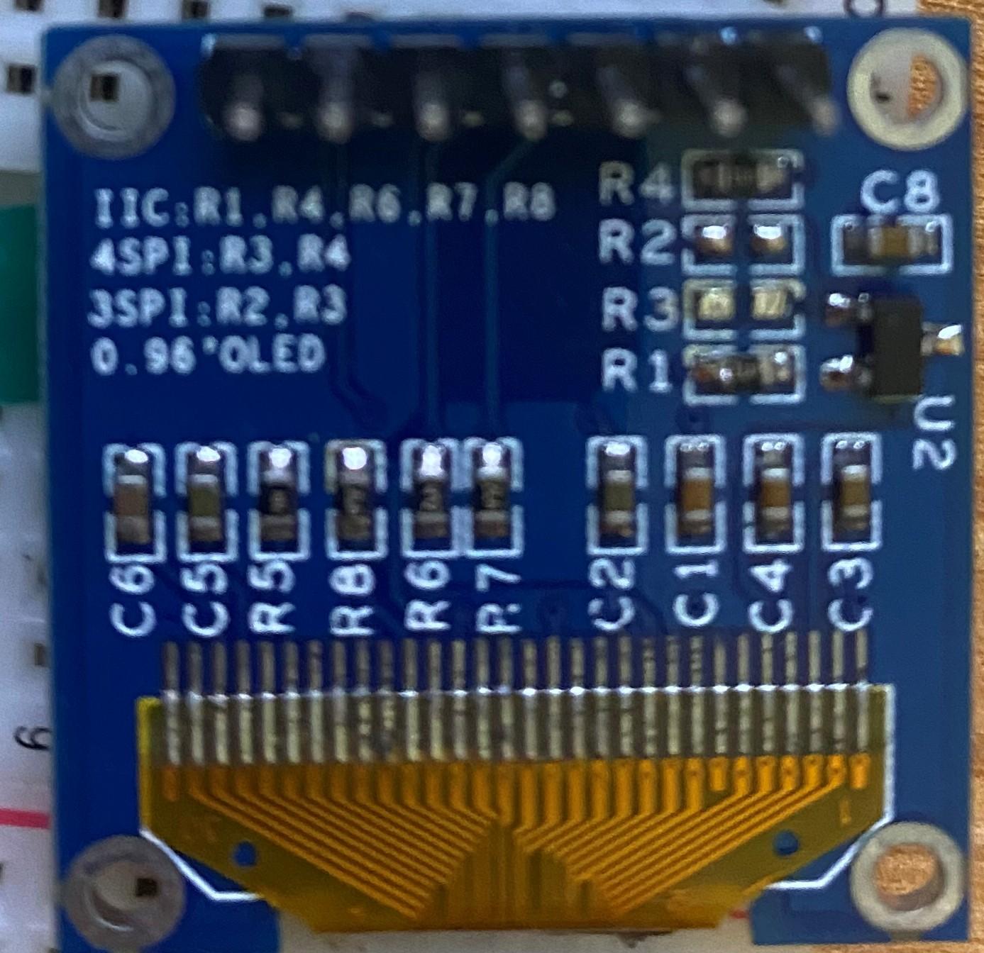
Finally got the dust off of my STM32F4 board to work on a project I started 3 years ago. Sad news, I cannot get these OLED displays working. They're factory wired for 4SPI, which I tried initially and no dice. Realized they might need to be I2C (IIC), so I moved/added the SMD resistors for that, but still no dice. Blank. Also edited the DEFAULT.NGC file to add: RESET_HW LCD "%C" LCD "@(1:1:1)OLED1" LCD "@(2:1:1)OLED2" LCD "@(3:1:1)OLED3" LCD "@(4:1:1)OLED4" LCD "@(5:1:1)OLED5" LCD "@(6:1:1)OLED6" LCD "@(7:1:1)OLED7" LCD "@(8:1:1)OLED8" Been several years since I've played around with building a MIDIBox project, and the last one was a LPC17 so I'm admittedly rusty as well as new to the STM32F4 board. What am I missing? Also, LD1/COM LED onthe STM32F4 board is red and blinks, is that normal? For what it's worth, the displays I am able to get working in Arduino projects, so it must be something I'm not doing right here. Img-4490.m4v

-
Hi I am in the research phase to build one of these beauties. I want to add an Ethernet port for the BLM emulator. Since the LPCXPRESSO is unavailable I believe I have to go with the MBHP_CORE_STM32F4. Has anybody used the MBHP_ETH sucessfully with this core? Is there a pcb/gerber for the MBHP_ETH available to buy? Cheers 6040
-
i am always interested into stm32F4 cores and stuff --- but RE_ take it - i am not interested into all off it --- but you will need all off it to build a seqV4 - so RE_ take it!
-
about the things above... well most of the things you dont need... you need 3x DINX4 1x DOUTx4 2x 2x40 LCDs 17x encoders a lot off buttons and LEDs 1x core 1x DIN MIDI much wires... a custom frontpanel big breatboards - to build a custom UI better go to V4, search the flearmarked forum for a "wilba" frontpanel pcb, and a stm32F4 core with discovery board, and a Midi IO Board Frontpanels you can order from "the beast" from UK.
-
 @tago Thorsten released the Windows toolchain - and it is working, just accessing the 64KB extra memory region of STM32F4 will crash the app, maybe it is a simple linker setting, but i investigated a while back and found no easy solution. On top, under windows, USB MIDI transfers are often very unstable, i.e. when flashing new firmware releases when developing you often have to either rescan MIDI ports or restart MIOS Studio for continuous uploads, which is really frustrating when developing. That is not necessary on a Mac, so you know my recommendation - you can get a used macbook air for ~300€ - while it's not as fast as an M1, it will do the job - imho for that price, it's not worth trying to improve the windows situation with the upper 64kb block, as the Windows USB stability situation cannot be fixed by us. Many greets, Peter
 -
@tago i switched to a Mac m1 a while ago and never looked back, it's awesome, as powerful as my 8-core i7, which cost a lot more, using a fraction of the electrical power at a higher single-core speed (a lot more responsive). You can still get a mini m1 for a bit above 600€, which is a steal for the offered package. The existing (old) toolchain/compilation works fine here, also working with 64kb "upper RAM" for the STM32F4. Upgrading the toolchain to the newest release would be some work, so i'd recommend going the established route - i had used a "free" Hackintosh before, so it's also a possibility to build e.g. MIDIbox NG on most common PC hardware, too. The MIDI implementation on Mac is also way better than anything Windows, so i did not investigate further. Best regards and enjoy! Peter
-
interested in stm32f4 and discovery.
-
 Hi, Any tips how to optimize NG to get better velocity performance? I'm getting very few velocities. I'm getting a very coarse velocitiy resolution. I'm using a STM32F4 core and have a 5 octave keyboard plus an AINSER8 attached. No menu or displays. I'm thankful for any tips.
 -
How much do you ask for the stm32F4 discovery board?
-
-edit- all parts are now sold! I have some kits for building Midibox Seq v4, all unbuilt/unused. SEQ CS pcb (smashtv) SEQ CS parts kit (smashtv) AOUT_NG kit (smashtv) STM32f4 core kit 2x MIDI IO kit I think I paid around £220 inc import taxes for the smashtv parts, the other bits were around £80. Asking £200 or make an offer. Located in UK, will ship WW.. happy to split shipping costs. Will add photos asap.
-
also have a stm32F4 discovery board link to pics: https://www.facebook.com/groups/synthdiy/permalink/10158778005481313/
-
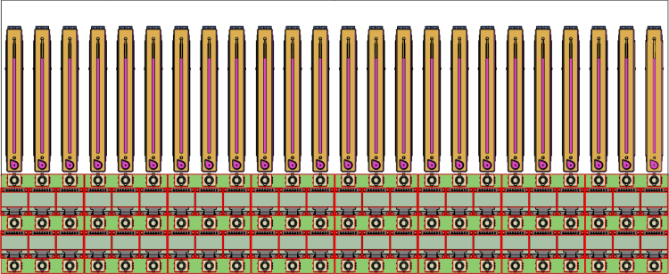
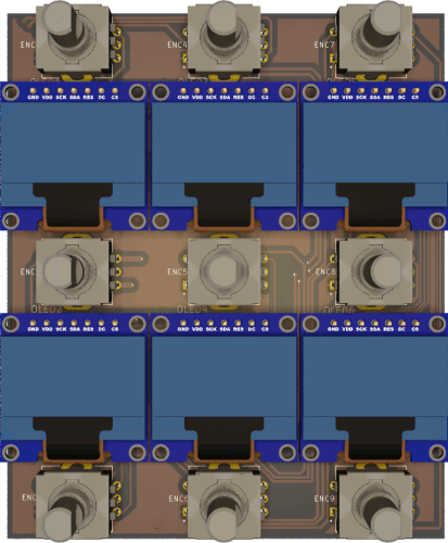
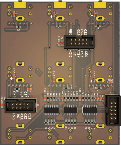
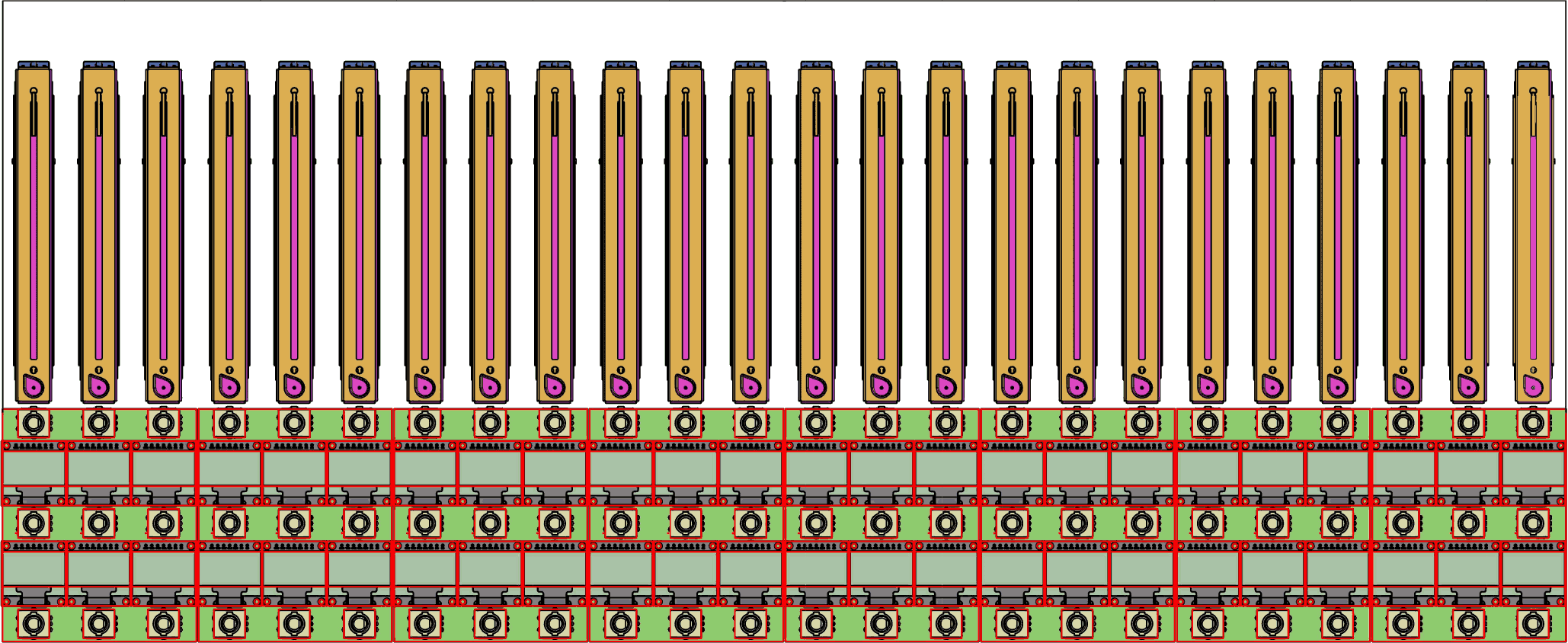
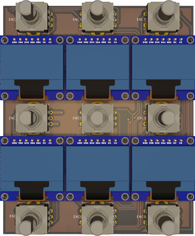
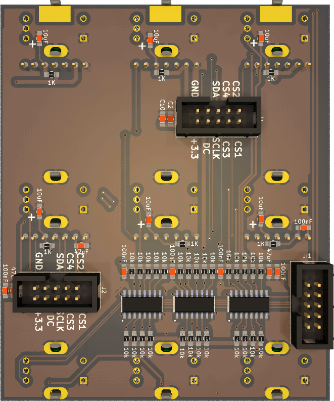
Lets get started... Goal is a midicontroller for Ableton live, at the beginning as simple midicontroller, maybe later to transfair Labels via max4Live to the controller... it will not a midibox-ng script, it will be a own program based on the MIOS-platform. Hardware first, i designed a 6xSSD1306 + 9 Encoder Board, that is scaleable --- i will use 8-10 off it, its documented here (incl gerbers): http://wiki.midibox.org/daw-encoder-display i already have the Motorfaders and the ready soldered and flashed mf-ng boards, i will controll them with a stm32F4 board... which also handles the encoders and displays. in order to drive the displays stable, i use latigid-ons display driver board. - this is also the offical discuss topic for this project (which is linked in the wiki)