Arkay
-
Posts
81 -
Joined
-
Last visited
-
Days Won
6
Content Type
Profiles
Forums
Blogs
Gallery
Everything posted by Arkay
-
All good today. Magically the missing 2 and a bit mins are back! :) Glad I got to listen to the full track! :) Cheers, Arkay.
-
Hawkeye. Another great track :smile: Loved it! But the video seemed to be cut off? Was enjoying things slowing down then BOOM. It just stopped @2:26 which I figure isn't the end??..
-
Lasercut Acrylic Case+ Frontpanel for SEQv4
Arkay replied to smokestacksproductions's topic in MIDIbox SEQ
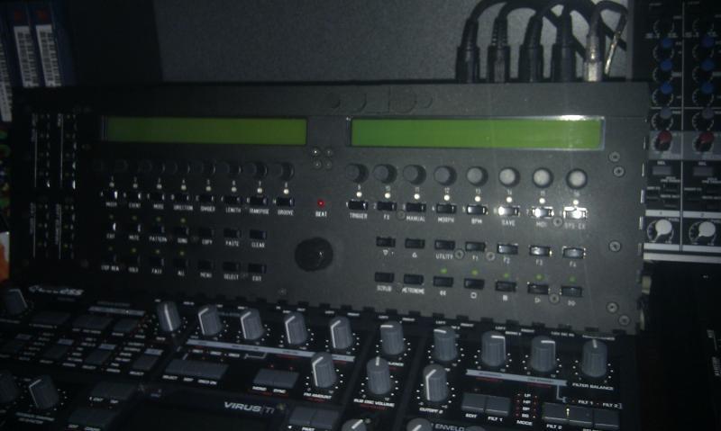
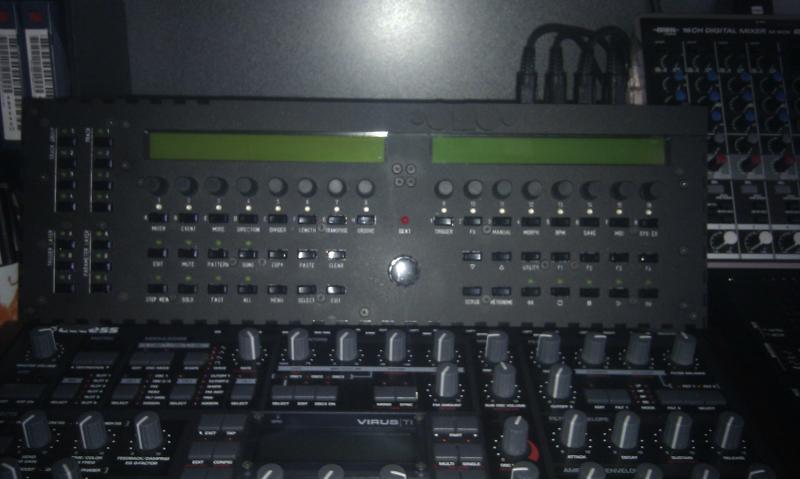
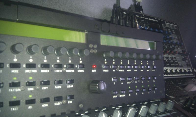
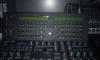
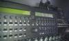
Just a few ideas for someone looking at doing one of these too. There's some ways you could modify the design. These are my observations from having also done a ponoko case from smokestackproductions original design in this thread (many thanks to him for the original idea/design work!): 1. As mentioned the case holes on the bottom should be mirrored. Depending on how you want to assemble your case you could go with no holes on the bottom at all and drill your own as you need them. (explained more in a minute). 2. The case may not need to be as high as in the original design. Depending on how you assemble it. 3. Adding additional holes for 4 more midi in/out's BLM is as easy as cut/pasting the original holes in the diagram. 4. I also moved my SD card slot to the far lower left side at the back and used an ebay SD card module on 10mm spacers (at it's rear), with the front of the module poking slightly through the case slot to keep it in place. I found when assembling mine that it was far simpler to attach the top panel only to the control surface, there was no need to use long screws and spacers from the top of the case all the way through to the holes in the bottom. The panel mounted directly to the control surface is very rigid and sits on top of the sides. With only 4 external nuts holding the panel/CS substrate to the sides the entire assembly is more than rigid enough. Doing this prevents having to try and line up a myriad of long bolts right through the case and makes assembly much easier, also providing more internally usable space in the case. It was nice to not have to mess with JB Weld for the panel mounting with this solution. My second point is that you could potentially take about an inch off the height of the case. If you chose to mount the core board to the base (not on 10mm standoffs), and move the corresponding midi in/out/lan/USB holes down to suit you could use as little as a thin washer to space the board from the plastic. Saving a lot in height. Equally the height of the panel/control surface board is only about 15mm when assembled, and can rest only mm's above the core and/or IIC boards if you install them. So the entire case can be much more svelt. I'd say 15mm for core board/case bottom (depending on how flat you mount the caps)+5mm clearance + 20mm CS/top == 40mm in height for the whole case. The current design is 65mm high. You'd have to calculate what is required in all measurements to achieve this but without threading bolts through 50mm spacers (x2), from top to bottom of case there is also no need for all the holes on the bottom and you can simply drill the few you need in the correct place to mount the core etc and attach the top panel to the bottom (in 6 places, each corner and 1 either side center) so that the entire case holds together. Those 6 holes in the original design already line up. So you could keep the outter 6 holes in the design on the base, and remove all others so you'd only need to drill the mounting holes for the circuit boards. Anyone attempting this case should also note that the plastic around the lcd holes is the weakest part of the design. I accidentally cracked mine by overtightening the screws that hold the top to the bottom. They should only be tightened enough to hold the structure together via friction. The space between the two lcds and the place on the right from lcd to edge are the weakest points. Fortunately I was able to glue mine back and I used some of the off-cut plastic from ponoko to make a design above the lcd's to cover the mistakes (not ideal but saved me reordering a new panel). Note that there's nothing at all wrong with smokestackdesigns original plans in this thread (apart from the mirroring of the holes). I just thought I'd throw in some options and ideas that I learned from having done one myself. They may or may not be useful to others. It was an easy process. I modified the original files in inkscape, created an account on ponoko, uploaded the design, selected the largest acrylic sheet ( No 3 size at 790mm). They cut it and sent it to me for $70. I then painted the text while the paper overlay was still in place. Cheers, Arkay. P.S. Some pics attached (taken on my phone), that give a good idea of what to expect with the finished product. I'll be putting a larger DK38 knob on the center encoder when I get one (purely for aesthetic reasons).
-
Control surface PCB for 16 encoders/LEDrings Bulk Order
Arkay replied to Fairlightiii's topic in Bulk Orders
Guys, With regard to the MBSeqv4 encoders. I also experienced the different "feel" for each of the 16 encoders. Some were hard, some were soft and the detent "click" seemed to vary in how solid/loose it feels. I found that their stiffness was a factor of how far down the knob on the encoder is pushed. I think if you set them down too far you can get varying levels of friction between the knob and control surface causing them to feel stiffer than they are (specially if the knob isn't perfectly round and/or parallel to the control surface). Once I played with mine and moved the stiff ones up a fraction from the control surface they all became much more consistent, easy to turn, with mostly the same feel. Might be worth seeing if those results can be replicated. I always lubricate the insides of the knobs before putting them on the encoders so they aren't too hard to readjust (or get off if you need too), as some fit way too snug. Since doing this the knobs have been much more comfortable to use and differences is quality aren't as obvious. Cheers, Arkay. P.S. This could also be relevant. I bought my MB6582 encoders from mouser, all bourns type, and had no end of trouble with the entire batch. Don't know why but they would skip endlessly, some worse than others, and I ended up having to desolder the lot and replace them. I then purchased the ones Hawkeye recommended in his build thread (I think they were ALPS encoders). There was a very clear and obvious difference in the quality of the 2 with the ALPS feeling much more solid and consistent. Having only used those 2 differing types I can say that I'd be wary of the bourns, particularly if removing the detents. That being said I didn't have any similar issues with the ones Tim supplies with the MBSeq kit, and I'm sure they are the same. But the detents are not removed in the MBSeqv4 build so perhaps as long as you don't open them you're in good shape. I've since decided that I prefer the detent anyway, even in the MB6582, as ilmenator suggest above, the input is digital and quantized. For me the detents add more clearly defined graduations for whatever element you're adjusting. It also makes troubleshooting encoder types much easier if the encoder still has the detent installed. When you can't feel the click it's very hard to see/feel when the bit pattern is changing when setting the encoder type in code (if you ever need to). -
kristal=, Will be happy to jump on this one as well. Need a datawheel and about 25 transparent reds. Just waiting on my password change email (forgot what it was), for the wiki before I add my details. Thanks for running this again. You're the reason my MB6582's and soon the MBSeqv4 look so good :D Cheers, Arkay. Edit: Wiki updated ;)
-
Sammich plays only the sounds from one chip in MULTI mode
Arkay replied to Taika-Kim's topic in MIDIbox SID
Tried making sure it hasn't somehow been switched to mono. I recently had a similar issue but found the sid engine had been switched to mono thereby causing the right sid to make no sound. It would make sense that it is setting related when the sound hardware is clearly correct in all other modes? Cheers, Arkay. -
Hey guys. Finally got this resolved so thought I'd better post the results for anyone else that goes through this. Was speaking to Wilba last week (he's been flat out), and didn't have time to look at my 6582 as yet, but he did loan me his SMD desoldering tool so I could have a go at desoldering the encoders myself. Hawkeye (sorry man), forgot to ask Wilba about the OLEDs but I have to drop the tool back so will try to remember then. Anyhow. Took the machine home and ended up not using the desoldering tool anyway. I desoldered a couple of encoders the old fashioned way, solder sucker, braid, and replaced some of the bourns encoders with the new ALPs ones. The difference was like night and day. I left all the new ones detented too. But on the old bourns I could barely see a difference between different firmware setups (encoder3 vs encoder4) etc. With these, and the detents in place, it was very simple to detect the correct firmware setting to select the right encoder type. I then proceeded to do the rest of the encoders. Some proved a little hard to get off but I had a technique and stuck with it and got there in the end. Sadly though in my exuberance after I'd re-soldered all 15 new encoders I had 6 not working and 1 led that had taken a hit. Turns out I had put a little too much pressure under the encoders to get some of them out and must have broken some tracks on the board. So it took me a little while to trace the circuit. I never found the actual breaks, but I did manage to solder 3 bypasses to fix all 6 encoders and the led. So at the end I had a fully finished control surface that works perfectly. I was wrapped!! Also managed to get the feedback pots installed. On the first 3 sids at least. I busted the 4th going for that extra half turn to line them all up! Grrr. Then I figured I'd never need feedback on all 4 anyway. Pots are an awesome mod though now I want some extra SSM2044s or something else too! I also noticed 1 small problem in that if I switch the filter to ext on sid 4L I lose output. I haven't tracked that one down yet, and aren't that worried as it works fine for everything else and that engine doesn't have the feedback pot anyway now. So I'll use it for a "Standard Instrument" channel and it makes no difference. I'm trying not to be anal and go for that "perfect, no problem build", that always results in causing more and bigger issues. So all things are sweet as they are. In the end this entire thread was the result of some bitch crap encoders, purchased from Mouser. Either I damaged them during removing the detents which is unlikely as I was very careful, or they were just crap to begin with. I favour the later. Moral of the story. There isn't really one. Bourns are used everywhere. I was just plain unlucky I think. One thing I did learn though is that there is no wierd stuff happening, no shorts or power oddities etc. It's very easy to convince yourself of inexplicable wierdness when in reality with electronics there's only so few things it really can be. I should've tried replacing an encoder much sooner. I'm in the middle of assembling my MBSEQv4 now, it also uses bourns encoders, but I expect they will be fine. I've decided though that I prefer them with detents anyway and if you don't pull them apart then if they really are rubbish you can send them back for replacement. Herein endeth the saga of the dodgy detent removed bourns encoders. Cheers, Arkay.
-
Great job :) Me likey!
-
Thanks Peter. Will do when I see him next ;) Cheers, Arkay.
-
Yeah. I know what you're saying. I may have misunderstood and/or quoted Wilba out of context. I think he was referring to the single encoder on the Sammich when he said that and it could have meant not soldering the larger tabs in place until proven that the encoders work correctly. So don't take what I said above as gospel. Perhaps in Hawkeyes guide he could suggest only soldering the 3 pins in place at first until they are all proven to work correctly when the larger tabs can then be soldered and the glue applied to lock the encoders up... If any encoders are proven to malfunction you could then either pull them apart (while on the board), and try to bend the contacts into a better position before glueing), or cut the three pins to desolder and replace the encoder before soldering the larger tabs. It sounds like common sense to me now but inexperience is what guides are there to aid I guess. Given the number of people that haven't had this issue it's clearly not common anyway. But all guides can always use more information from problem installs... :) Cheers, Arkay.
-
I still haven't sorted this. Very luckily for me though I live about 10 mins from Wilba's place and he kindly offered to take a look at it for me. I already ordered 14 replacement encoders (the same as Hawkeye mentions above), to put them in my MB6582. Wilba has these too and I imagine when it comes time to troubleshoot my machine that he'll end up having to remove and replace each encoder with these new ones. But until he's looked at it it's all conjecture. There might be some other issues. I don't know. When he has had time I'll be sure to post the solution onto the thread as I know what it's like to finally find a thread that completely explains your issue but never says what the resolution was. Stay tuned. Cheers, Arkay P.S. For Hawkeye: I was following your guide when I assembled the CS (great guide!), and I remember testing each of my encoders to make sure they worked. Both with a multimeter, after removing the detents, and then in the machine, after installation. They did of course function in that I can move any value from fully off, through it's range to fully on, whatever it is (it appears to work as designed on every encoder). The problem here is only on fine movement when trying to set specific values. I thought everything checked out and moved on because I was testing for function, not control, having no real idea of what the synth is like to use at that time. I ended up soldering them in, and glueing them down, BEFORE I realised I had this problem. Both those actions make this problem challenging to fix now. Can I maybe suggest a line item in your build guide to suggest that fine control of each encoder (setting specific values), should be checked before soldering the side tabs (the large ones) in place, and before glueing the encoders shut. As Wilba has since suggested he never solders the large tabs, only the 3 active pins on the encoders (which is already strong enough to keep them in place), as it makes them difficult to remove later should you need to. Just a suggestion but it could save some people some grief ;)
-
My stuff finally arrived in Aus on Thursday too! Yay! Thanks Thorsten ;) Cheers, Arkay.
-
Thanks Freddy! Much appreciated. Paypal info has been PM'ed. Cheers, Arkay.
-
2 X MBSEQv4 1 X MB6582 for me please ;) Cheers, Arkay.
-
ok. Got and wired up the new display tonight. Display works fine, just like the last one. Encoders are still shite though. Don't know what to do now. It's so bloody frustrating... Maybe I can write some code for the raspberry pi so I can plug in each of the encoders on the control surface and see what they output running from the pi's 5v power with the base board removed. If the encoders don't jitter then that will prove the interference is coming from the base board and that the encoders are ok. That will stop be desoldering them all. If it does prove the CS is fine I dunno what I'll do then though. Grrrrrrrrrmumble mumble... Anyone live in Melbourne Australia and would like to try out their CS on my baseboard or my CS on their baseboard?
-
Can I please add a "me too" to this thread just in case someone has two! Cheers, Arkay.
-
No worries :) It was a good line of thought. I've found a few threads that looked promising only to find that Mios (vx.y) fixed the issue and the information is no longer relevant. I appreciate the help! Hopefully when I get the new display everything will be fine and it was just a short caused by the lcd. Cheers, Arkay.
-
Agreed :D I just got an email from wilba for a sammich kit I asked about (before I built the MB6582), I'm tempted to buy and build one as well so I have more SID action!! :D
-
True. I had a look at the debounce code and there didn't seem to be much to modify. I'll have a better look though. Interestingly, I replaced all my connections between the base board and the CS the other day as the way it was soldered wire connections could break too easily with the amount of moving about I need to do at the moment. It's much better now but after I did this I was messing about, had all 4 SID engines screaming and the LCD packed it in on me. Lost everything but the top left quadrant of the LCD, then eventually it died completely. This leads me to believe (hope), that it was shorting on the board at one point where it may have been possible if a single pin had gotten through the solder mask on the LCD. I've ordered another display which I'll have in about a week. So I can re-test then. I'll make a new LCD cable as well and mask the LCD better. With any luck the encoders will be fine testing the machine with the LCD not mounted etc and I'll have found the issue. I didn't pick it up during assembly as turning the encoders changed values up/down without issue, it's only the fine control and trying to set a specific value where the problem is obvious. These encoders are not weird in any way, they are the bourns encoders Smashtv sells and the ones Wilba recommends in the Wiki so they should be fine. I'll be back with an update in a week or so :) Cheers, Arkay.
-
Lasercut Acrylic Case+ Frontpanel for SEQv4
Arkay replied to smokestacksproductions's topic in MIDIbox SEQ
Thanks for the info. Will look into ordering one shortly too. Once I sort out these MB6582 issues I'm having and get into the SEQv4 build. Cheers, Arkay. -
Sorry. You're correct. I just wrote it incorrectly late last night when I posted that post. I am getting 4 different bit patterns that are opposite based on direction so at least that one I tested was working as expected. Cheers, Arkay.
-
Thanks for the ideas :) I actually plugged one in on a breadboard with a couple of resistors/leds and a 5v source. Realised I didn't need the Pi as well. Turns out the quadrature and the encoder works fine. It is ABC wired, but so is the board, so that is all ok. Testing revealed: for one direction (I can't remember which): 00 01 10 11 and the other: 00 10 01 11 So things are as they should be. This happens per detent (I also tested an unused detented one), everything sits at 0 when the encoder stops at a detent. Once I can find my aligator clips I'm going to try the same test on my breadboard with the encoders that are on the CS with the MB6582 powered off. I can test at the encoder and also at the board connectors that go to the base board. That will tell me if there's any fault with the encoders. I do notice some are better than others. Once I've done that and I'm expecting they will be ok, so I'll be pretty sure then that it's some sort of earth issue with the commons being dirty somehow.. Some noise in the power somewhere perhaps. How I isolate that I don't know. I have noticed that the piece of electrical tape I put on my LCD to stop it touching the board on the non wired side is fine, but on the side where the cable is connected the tape doesn't go all the way across. I'm going to have to pull the CS apart again to check if the LCD could be shorting on the board somehow. Bit frustrating. But I'll get there. Cheers, Arkay.
-
Sorry to keep posting in this thread people but I just read something interesting about bourns data sheets. I just checked the schematics and the CS board layout has the pins set as A C B for the inner holes and A B C for the outter ones, depending on the type of encoder and size of the encoder used I'd guess. Where A/B are the 2 channels in the encoder and C is the common. The datasheet here: http://www.bourns.com/pdfs/pec16.pdf Suggests the pin ordering is A B C!, but from everything I've seen the board is wired for A C B, where C is common and A/B give you the directional information on a 4 bit turn. Have to check this but if the bourns encoder uses the smaller pins and the data sheet is correct then everything would be all messed up.... Or perhaps I've gone insane. Occam's razor suggests the later. Here's the thread that raises the issue with these bourns data sheets : http://www.eevblog.com/forum/projects-designs-and-technical-stuff/bourns-rotary-encoder-with-detents-no-gray-code/ I'm going to plug one of these into my raspberry pi via a breadboard to see what the hell it's really configured for but could it be possible that the MB6582 is reacting with the jitter I'm seeing because of this, or am I barking up the wrong tree? It would sort of explain why the values can go up or down while only turning in one direction. However the value will always go fully up or down eventually when turning it in the correct direction continually. Slow turning results in more jitter though and it seems at times like the encoder shorts (or rather), A and B pins are grounding at the same time more often than they should), perhaps that is a side effect of this.... Cheers, Arkay. P.S. I've ordered 15 alpha encoders anyway as I've lost all confidence in these bourns ones but I'm still not keen on desoldering 15 encoders......
-
Lasercut Acrylic Case+ Frontpanel for SEQv4
Arkay replied to smokestacksproductions's topic in MIDIbox SEQ
Any more info on this one. Would love to see some more pics of the completed unit. If you could describe what files you need to send where, i.e. how to order it, that would be an awesome help too. I have no idea having never done it before? Thanks! :D Cheers, Arkay. -
Ok. Little more research and while I feel I'm getting closer I'm still confused. I found a page on the wiki that describes the various types of encoders. the page is here: http://www.midibox.org/dokuwiki/doku.php?id=encoders&s[]=encoder&s[]=types On that page the bourns encoder mentioned is the PEC11 (which is no longer used). The original Wilba MB-6582 control surface parts list wiki page found here: http://www.midibox.org/dokuwiki/doku.php?id=wilba_mb_6582_control_surface_parts_list suggests to use Mouser part #: 652-PEC16-4220FN0024 (PEC16), which is what I purchased : http://au.mouser.com/ProductDetail/Bourns/PEC16-4220F-N0024/?qs=%2fha2pyFaduidMAYXvh4P%252bOmugSqGmJEMvgB8DnSDzKia7TN8Tt6xRCYrHqKqgnwK from the data sheet on that encoder: The PEC16 is a 24 detent, no switch, flat shaft 24 detent per 360 degree encoder. The data sheet can be seen here: http://www.bourns.com/pdfs/pec16.pdf This page: http://midibox.org/forums/index.php?app=core&module=attach§ion=attach&attach_rel_module=post&attach_id=5566 Shows the various quadrature possibilities, and also suggests how you can specify in the code any combination of encoder based on its data sheet information. (It gives an example how to replicate DETENDED_2 for instance.) I'm trying to figure out from the data sheet if the switching method of this encoder matches any of the predefined ones in the code, or alternately, what values I can try to tell mios about the intricacies of this encoder. But I haven't quite got my head around it yet. Perhaps someone could look at the data sheet and the last link and suggest how they match up. Note that the diagram from Thorsten shows counter clockwise at the top where the datasheet shows counter clockwise at the bottom. I can't see that this should be necessary as this encoder is the type Wilba recommended in the control surface parts wiki so perhaps there is something else amiss but I've looked over the board and by the way it's acting I can only assume that it's a firmware (software), related issue with these encoders and their jitter. I've just about researched this to the limits of possibility. If I can work out what these diagrams mean I can try different values but ultimately there are only 8 hex values according to the last link above (0x01,0x02,0x04,0x08,0x10,0x20,0x40,0x80), so I can always create firmware for every possible combination of switching and test which gives the best result and possibly fix it that way. If I'm reading the code in mios.h correctly along with the data sheet then this encoder should trigger on 1/5 (A=1,B=5) which gives 0x022 same as DETENDED_2 which I've tried and had poor results with. Maybe I should buy some ALPS encoders and de/resolder. But I could have the same problem with them too.... Arrrrgggghhhhhh.