Phatline
-
Posts
1,285 -
Joined
-
Last visited
-
Days Won
72
Content Type
Profiles
Forums
Blogs
Gallery
Everything posted by Phatline
-
Konga Trigga: i am on the PCB-Design right now... not finished, just at the start, but this is the UI-Arrangment i think (10x10cm PCB) has 3 Trigger-Mic Inputs (which are 0,5€ Elektret Capsulas), each for one Konga Drum. The 3 Pots are the preamp-Gain, they have to set only once... Konga Trigger then preamps the signal > the signal gets buffered mix - down to a Audio Sum - which can be use a other way (recording, efx...) how ever this is untested - and not part of the deal now... the preamped Signal then get rectified, and filtered, and go into a Schmitt Trigger, which transfair it to a 0 or 1 Logic Level > this goes into the Microprocessor: ---since dipcore has only 2 AIN > i decidet to mix down all 3 MIC and feed it into 1 AIN... maybe its not accurate Velocity then --- it has to be tested in real world, like many other functions in this shematic.... in the microprocessor (dipcore) - software functionalitys: step-sequencer (chooseable tacts 3/4 4/4 5/4 6/4 7/4 8/4...) whith just a few steps - lets say 16steps which one of the the triggers now Count the Step-Sequencer, and which one just retriggers the Sequencers Notes - is set in the Menu for this song (saved on SD) The Step Sequencer is a 2 Channel - bass and poly. they are counted equal, but we can decide which of the triggers trigger Poly or Mono Midichannel out. a connected Keyboard on Midi-In1 is input for the Step-Record, - on the Menu i cand activate it as "REC-only" or "REC-&-Trigger" - so it just sets the Notes, or it also Triggers the Notes to Output to Midiout... There are differnt Modes for the 6 Buttons: one of it is the Perform Mode > where we can shift the Sequencer arround, have record buttons and so on.... The LCD is primary for the Routing-Setup, and a displays for different Modes - for example, it shown in Big Letters the Actual Step of Sequence this is just a start - (and NO its not the last 10x10cm Format Project ;) --- a Multiband-Distortion is also Planned - and then its enogh for a while)


-

dipCoreF4 and dipBoardF4, a compact Core.
Phatline replied to Antichambre's topic in Design Concepts
did i connect the OLED-Display right?: i took this as blueprint: > it says CS0 to CS --- but on dipcore i see only CS1 --- doesnt matter?

-
thx - looks good - i converted it to kicad library: oled-kicad.zip
-
lpccore gives 3.3v on midi while stm32+midio gives 5v so xoxbox have problems with this non standard low voltage - try the stm core.
-
i have this standard 7-pin OLED 1306 Displays: and i want them to include it into a kicad project (i can translate eagle to kicad) does anyobody have footprint and shematic file? i found in internet, some files but all of it are OLED-Foil-Connector to a PCB where all the Foil-Wires resulting into this 7-Pin Breakout - that i dont need. i have already a Display and the PCB where it sits on it - and from there i get a 7-Pin Connection to my Project PCB. short i need a Library for the complete Display shown in the Video above. anyone? thx.
-
dipCoreF4 and dipBoardF4, a compact Core.
Phatline replied to Antichambre's topic in Design Concepts
thx! so PB6-J4A.SD PB7-J4B.SD for example? fine do i have to change anything in mios itself - or is it done in the main app/mios.config file? (i know J5 and J10 are GPIO labeled on standard core docu - but J4 is for IIC) -
dipCoreF4 and dipBoardF4, a compact Core.
Phatline replied to Antichambre's topic in Design Concepts
hey i am working on a new project "Konga Trigga", and i want to reuse the DipCoreF4 for that again... since it is really handy i need 3 Digital Inputs (used as Trigger inputs - feedet with Schmitt-Trigger Digital Signals) i dont want to connect them via a slow shift register - since it is trigger > it is time critical. As far as i can see i can use J5.A0(PA1) + J5 A1(PC5) > and set them in Mios as Digital Input, makes 2 so only one Digital input left - is there any other Pin i can use as DIN? (LED.1, LED.0 for example?) User.Butt (PA0) > is for Bootloader Switch - maybe that one? -
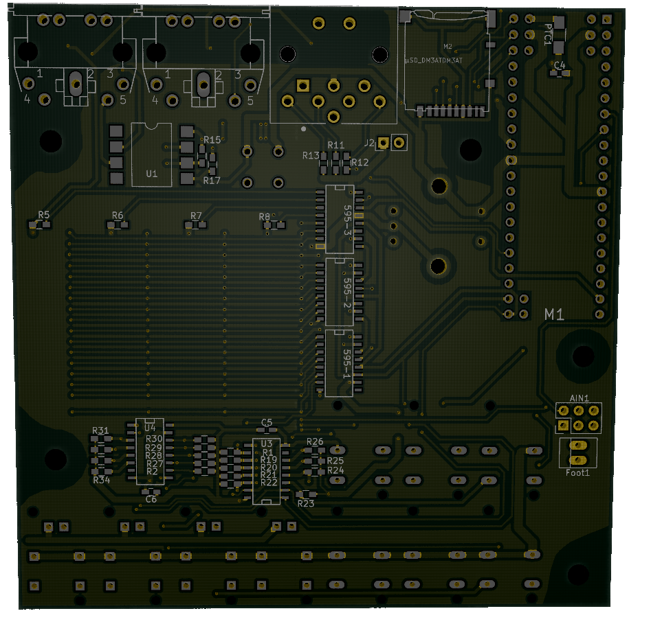
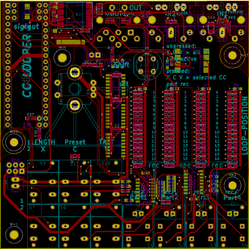
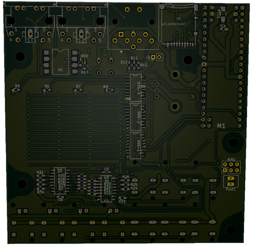
i addet the suggested DIN7 - thx. i ordert the prototype pcbs - should get it in 8-25days ...next thing is mouser boom... at least 8days time for that. these is the final proto-design:
-
i have one, already assembled, only thing left is a case... but cant ship to US - yesterday i payed 83€... and the receiver will have to pay also import taxes. good look.
-
interesting - please upload some pictutes
-
 its a kongo trigga mic ( mount it in/under a konga drum . the drummer retriggers my on organ set notes ) the concept is working and i plan a 3 voice konga 10x10cm pcb for it (here it was a quick prototype)
 -

-
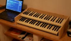
 old-home-organ-into new case - midified
 -
 old-home-organ-into new case - midified
 -
-
DIN7-270° ... to hard to source.
-
good input, will integrate that!
- 27 replies
-
- 1
-

-
- cc-recorder
- controlchange looper
- (and 1 more)
-
nice ! @_sysex: the callback if needet could be a problem because of only one Midi out din socket... the second out is only available as 3pin header. the houseing will be very flat so no place to mount. maybe with a 3.5 jack or something...
-
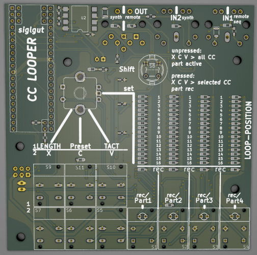
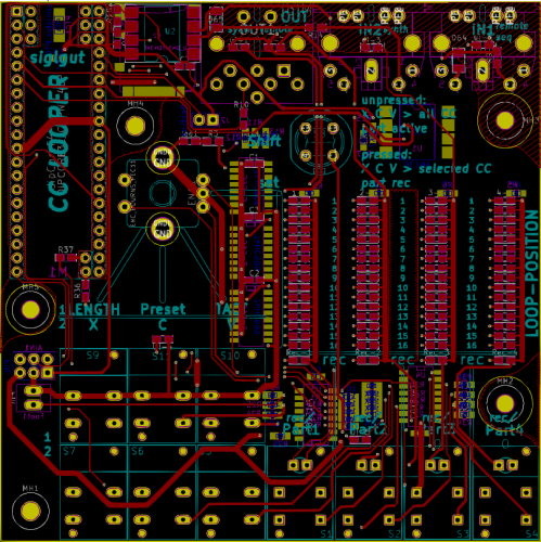
hot glue on the usb socket. and a big hole as usual no problem. planned is remote record for the 4 parts. as already implemented in the cliplauncher of triggermatriX (cc command) also on device is footswitchjack which act as record/play button for currently selected part. ... i will screw the jack directly on the housing. a footswitch turnt out to be "handy" :) to tweedle and record multiple ccs...
-
loopa xmas.... triggematrix. a keyboard ... loopa ... a cc looper looped nordrack 3... dupdiduu ;) its a remote device built to be a midiclock slave. it takes clock.start stop as usual. cc looper get remoted via cc (from the master 4 examle loopa in my case triggermatrix by songparts selecting like ableton) select bank and pc (pc as standard pc message + bank via cc..). store and load. set the tactsystem 3/4 4/4 5/4..... havenot need sysex so far just a few ccs . all the other functions (play record looplength copy clear paste whole sets or single selected cc automations are set on cc looper itself and will be saved on sd card as pc loadable file - which itself has non-standard :)
-
dipCoreF4 and dipBoardF4, a compact Core.
Phatline replied to Antichambre's topic in Design Concepts
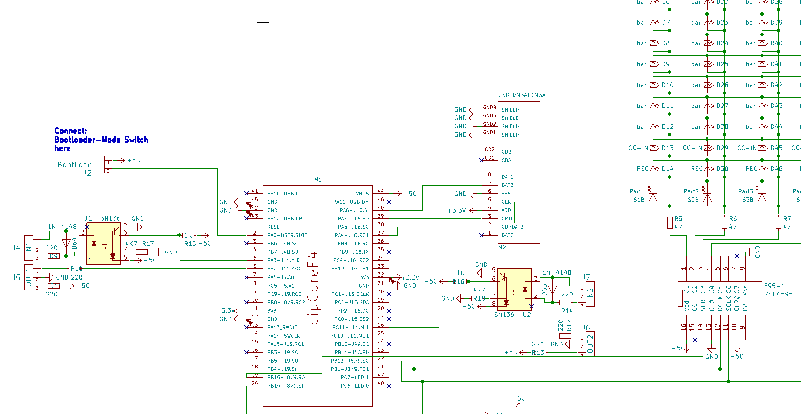
hi. since i need a few Extra LEDs to light up the UI, i was searching for the Onboard GPIO - i found PC6+PC7 > perfect. > on DipCore PC6+PC7 you handle as LED (DOUT) - how to call them in MIOS? > as Board LEDS? aka "MIOS32_BOARD_LED_Set(0,1);" ) > see http://www.midibox.org/mios32/manual/group___m_i_o_s32___b_o_a_r_d.html#ga46e21f1170f1876435f40d65977c6a83 > the PTC you used on DipCore what SMD Package is it? ( i want take the same as on DipCore... dont want to buy 2 different parts) > since i will be ready soon with the cc_looper - will order Protoboards for it the next days - i assume nothing changed on the Pinout of the DipCore until now > so i can order? have a nice weekend - mike -
i overworked the whole thing - now it operates with the "dipCoreF4"
-
dipCoreF4 and dipBoardF4, a compact Core.
Phatline replied to Antichambre's topic in Design Concepts
ah ok... i just add a ptc"fuse" on my design. so i can use vbuspin44 of dipcore to power the shiftregisters with no troubles. all clear -
dipCoreF4 and dipBoardF4, a compact Core.
Phatline replied to Antichambre's topic in Design Concepts
- to bad that you not connected a single Pin on the 5V area... to understand that right: * you use dipcore like a PIC18 - a PIC back in the days needet external power (but a pic also has no usb connector on it ;) and more then 40pins ) * on the dipcore is a usb-socket - but you dont want to power the dipboard with that USB (and all J8/9...). * on the dipboardf4 is no usb-socket - and you power your modules and the dipcore with dipboard, the 5V you need - you get from a Walladapter connected to Pinheader... or you wire a external USB-Modul on dipboard (but as you wrote, the usb dont get better over 10angels...) . instead of routing USB over several connectors and traces, and by doing so - reducing my Space for Rear Connections on my Main-PCB i will solder a wire to R3 and connect it to my motherboard, nasty, but when i read your shematic right - it will do the the job. -
dipCoreF4 and dipBoardF4, a compact Core.
Phatline replied to Antichambre's topic in Design Concepts
i know that the HCT541 is onboard, i already connected the 165 and 595 datalines...that was no problem. i dont know what you mean-it is not clear for me: with the VBUS and external source... > i want to plugin a USB-Cable, and power my Core and the J8/9 with it * i dont use a Dip-Expansion-Mother-Board - i plug the DipCore into a UI-PCB where all shiftregisters and all other components are already on it. * a simple example Circuit: a 595 and 6n136 are connected to the DIP-Core, where do they get 5V? (from the VBUS-Pin? is this the source?) thx 4 help