ilmenator
-
Posts
2,305 -
Joined
-
Last visited
-
Days Won
37
Content Type
Profiles
Forums
Blogs
Gallery
Everything posted by ilmenator
-
I'd be very interested in this, too - I checked some old posts of yours, but all the links to membres.lycos.fr are dead... Best, ilmenator
-
Alternatively, you could go for an acrylic panel lasercut by Ponoko. Way cheaper, but obviously not as sturdy.
-
All I can say is that it used to work on my side - that was before I made the switch to LPC17 based core, so I cannot test anything with current firmware versions.
-
Looks like Adam's boards were made at OSH Park as well - yummy, purple!
-
Sale or giveaway of slightly defect LPC1769 (No network)
ilmenator replied to audiomobster's topic in Fleamarket
Isn't there documentation available that tells you what value C63 has? Then order the part at Reichelt, this is not a super miniature part, it is an easy fix! -
Well that depends on demand. I will monitor this thread and see how things develop.
-
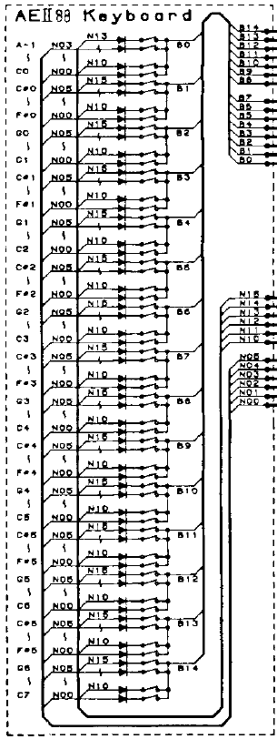
Thanks TK, I could finally get my hands on the schematics of the keyboard, and it all makes sense - but, the sad part is that this keyboard seems to be organized slightly differently than the Fatar ones, see below. I am sure this can be accommodated for in software!? It looks as if the keyboard was not split into separate halves, so we have 2 different matrices (one for the "early contact", one for the "late contact"), each of which is in a 6x15 configuration. Best, ilmenator Edit: I had it wrong again, this is now hopefully how the keyboard is organized...
-
Hi, I have an old Korg C-26 electric piano that has broken down, so I'd like to give it a second life with MIDIbox KB. The keyboard scanning schematics look very much like Type #2 Keyboard EXCEPT that it has common cathode instead of common anode diodes configuration. In other words, the diodes are inversed. Now, I could remove all diodes and solder them in the opposite way, but I'd rather have this solved in software if possible. How? Thanks, ilmenator
-
Looking good - is that the minimum size of case that is possible?
-
Das ist mit der normalen Hardware möglich und kann programmiert werden!
-
Das "MIDIprotokoll" hat mit der Hardware erstmal nichts zu tun. Du kannst mit einem "Regler" ja auch unterschiedliche MIDI-Controllernummern senden, wenn du das entsprechend programmierst. Oder mit unterschiedlichen "Reglern" dieselbe Controllernummer. Vielleicht solltest du erstmal noch ein bisschen auf ucapps.de stöbern und die Projektbeschreibungen lesen, bevor du bestellst. Beim Lesen werden sich einige Fragezeichen in Luft auflösen - dafür kommen dann neue, konkretere Fragen ;-), die wir gerne beantworten!
-
The power supply is plenty and the switching frequency will not affect the problem. Double-check all soldering joints at the shift register ICs. I guess you have forgotten one, hence there is a floating voltage on some LEDs which causes your problem. A hi-res picture of the underside might help spotting the problem (but this board is large). Edit: Oh, and also check orientation of the resistor networks (RNs)!
-
As far as I can see from the datasheet you'd need a software "driver" on the MIOS side of things for this to work properly. As the board is now, only the encoder will work without modifications, but not the LED ring.
-
I see what you mean now - at first sight it looks like a solder-/component-side confusion, but it is more complicated than that :sad: .
-
Don't blame it on Kicad... I don't fully get what the problem is, but maybe you simply went for the wrong component or module?
-
Yes, there was a user project but AFAIR there was a 6-voice limit due to slow SD card access.
-
Sounds like a proper (multiple-voice) MIDIbox sample player would be feasible soon.
-
Es sind alle Gerber-Layer vorhanden - gerade nochmal nachgeschaut. Mehr brauchst du nicht :smile: . Die kann man übrigens auch mit anderen Tools öffnen, mein Favorit dafür ist der Gerber-Viewer von KiCad. Da lässt sich die Anzeige auch bequem zwischen inches und mm umschalten. Edit: PDFs sind im zip-Paket übrigens auch drin. Viele PDF-Tools können auch Abstände messen.
-
Mit "Ekstrahieren" meinte ich auch eher, dass du mal auf die grafische Anzeige schaust, die Eagle dir darbietet wenn du das File damit oeffnest... Dann bewegst du den Cursor an den Platinenrand, setzt die Koordinaten auf 0 und schaust nochmal auf die Koordinatenanzeige, wenn du den Cursor in die Mitte der MIDI-Buchsen bewegt hast. Ansonsten scheint die Antwort auf deine Frage eher "nein" zu sein. Und: sind wir nicht in einem DIY-Forum?
-
??? Natürlich liegen Daten vor, du musst dir nur die Mühe machen sie zu extrahieren! Die Abstände der Bohrungen in der Horizontalen kannst du dem Platinenlayout entnehmen. Die vertikalen Abstände, zB von Oberkante Platine aus, findest du in den Datenblättern der verbauten Komponenten - das ist im Zweifelsfall also sowieso von deinem persönlichen "build" abhängig.
-
Das Eagle-Layout sollte doch auf ucapps.de vorhanden sein - lad dir einfach die aktuelle (Demo-)Version von Eagle runter und schau selbst nach. Dann hast du es auf den Zehntelmillimeter genau!
-
Yeah, but still: what list?
-
I went through most of my basement but couldn't locate them. I *should* have a box with numerous leftover PICs, but where? So, for now I'm afraid I have to disappoint you. I'll get back to you in case I come across them - sorry.
-
I'll check when I get home tonight if my memory failed me or served me right :smile: .
-
I am almost sure I have one somewhere - but where are you located?