goyousalukis
-
Posts
387 -
Joined
-
Last visited
-
Days Won
5
Content Type
Profiles
Forums
Blogs
Gallery
Everything posted by goyousalukis
-
Hi, A big (all-in-one) control surface PCB is nice to have, but it is not absolutely necessary. You can build the separate modules and connect them together and get the exact same functionality as the MB Sequencer. You just have to figure out how to mount the buttons, LEDs, and encoders.I don't know if anyone here is going to want to design a "on-off" board. That is a lot of work (well beyond my abilities:). As far as power draw goes, you can power a MBSeq from an external source. I have mine powered by a 5V 10 AMP power supply - this one: https://www.amazon.com/gp/product/B005T6TLMI/ref=oh_aui_detailpage_o02_s00?ie=UTF8&psc=1 Of course I don't expect it to draw anywhere near 10 AMPs. If you post a link to the displays you plan to use, we can take a look at the specs. Regards, Justin
-

Question about required pcbs for this project
goyousalukis replied to AMenard's topic in MIDIbox SID
Hi Amenard, For the MidiBox Sid with Wilba's control panel, all that is needed is the main and control surface PCBs. Some builders add an AOUT board so that they can add CV outs to control analog stuff, but that is not necessary. Everything you need is on those two boards. Hope this helps, Justin -
Just a guess, but I would inspect all the solder joints on the IC's. Since the buttons are connected with a matrix, a stray blob of solder or some other bridge could cause weird results. I could swear there is a firmware you can upload that tells you which pin each button is connected to, but I don't see it in the troubleshooting section of the MIOS8 uploads.
-
Thanks, that helps a lot. I considered the idea of a slide switch also. I appreciate the link...
-
Quick question: It is my understanding that I can plug a USB keyboard directly into the SEQ to control transposition, Arp, CV outs, etc... Since the USB keyboard is powered by USB, I would assume that I need to bridge Pin PA9 to 5V in order to give the USB Keyboard power via the micro USB. Is this correct? I am using my own MeanWell 5V power to power the SEQ. Is there any issue if I bridge the pin and then connect the seq to a PC via USB? I am worried that I could fry something if I use my own power supply and then plug the micro usb port into my PC. Thanks, Justin
-
Hi, thanks for this great enclosure. I am unable to open the scale-corrected version in Inkscape, and I don't have Illustrator. Also, I get the error message at ponoko when I try to upload it. Is it possible to get an updated version, or perhaps a DXF? Thanks, Justin
-
I might be willing to build you one if you are interested. I am just finishing up mine, so I have current parts numbers, etc... Send me a PM if you are interested, and I will run the numbers. I am located in Texas, so shipping cost would be a factor.
-
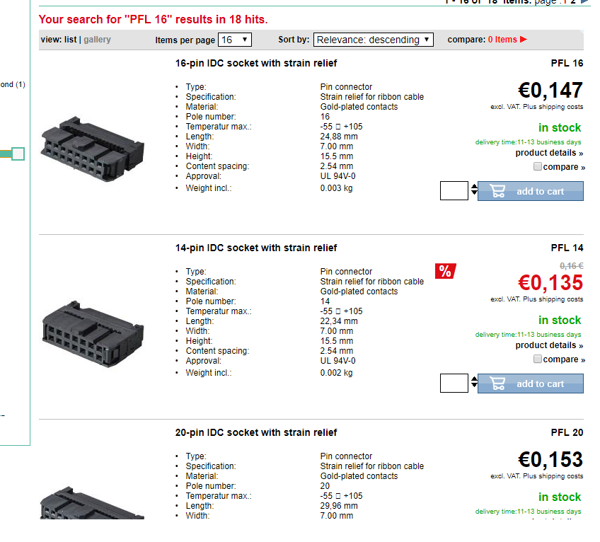
But like Gerald said, check out ebay, amazon, etc. I got mine at Amazon in sets of 10 for cheaper.

-
The part numbers for Reichelt are PFL 10 and PFL 16. I tried to post a link, but it didn't work.
-
Chris, I've been wanting to do the same thing. I have a bunch of piezo pickups like this: https://www.amazon.com/Vktech%C2%AE-Trigger-Acoustic-Pickup-Guitar/dp/B016CW1WK6/ref=sr_1_1?ie=UTF8&qid=1522070751&sr=8-1&keywords=peizo I've made several contact mics for acoustic string instruments before with piezos. What you sandwich the piezo between will change the response. I was thinking I would cut up a mouse pad to start with. Maybe back it up with a piece of thick foam. I'd imagine a MB128 could be directly hooked up to a piezo via an AIN input board. I'm sure it has been done before, but I haven't seen it. Justin
-
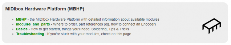
Hey guys, TK gave me wiki access, and I have been chipping away at some minor stuff. I've been adding Mouser parts where they are missing, and I added pages for the Ethernet, Line Driver modules, etc... I would like to make a small change to the start page of the wiki. Currently, there is the section for the MBHP. Under it, there is "MBHP - the MIDIbox Hardware Platform with detailed information about available modules" and "modules_and_parts - Where to order, part references (eg. how to connect an Encoder)". The second page has all the parts lists and schematics, and the first page even links to the second. I think it would be better if all the info for each module was listed on the MBHP page, and the second one would be about the parts in general and where to source them. Please let me know what you think? Justin
-
Is this what you need? http://www.ucapps.de/midio128/midio128_v3_scanmatrix.pdf
-
Also, I have old DIN/DOUT boards that I made back in 2002 that I am using with my new MB Sequencer V4 (STM32F4 Core) with no issues, and no changes.
-
Hi, I don't quite understand your question, but I will give it a shot. There are two main versions of the DIN board. The newer version has 4 10 Pin Headers - each has 8 inputs available. Here is the schematic: http://ucapps.de/mbhp/mbhp_dinx4_r5.pdf The older version has 8 5 pin headers - each header has 4 inputs available. Here is the schematic: http://ucapps.de/mbhp/mbhp_dinx4.pdf Functionally, there is no difference between the two designs - they can be interchanged. The newer one is better because it is easier to quickly make a 10 conductor cable with ribbon cable and IDC sockets/headers, versus crimping Molex connectors on the 5 pin version. Hopefully this helps a bit... Justin (EDIT) Another change between the two is that the newer version has the ability to use the resistor array instead of individual resistors.
-
That's good to know. I actually had a hard time finding a smaller SD card!
-
I know for the MB-Seq, the SD card is formatted with FAT, and because of this, only cards 4GB and smaller are supported. I don't know if this is the case for NG, but something to consider.
-
I guess if it were my keyboard, I would prefer to use the MB-KB and make it a regular midi keyboard again. Then I could hook it up to whatever midi stuff I wanted, including a softsynth on a raspberry pi. That being said, I hope it works out for you!
-
Well, my take on that would be, if you are willing to write all the code yourself and implement it, then go for it. If you want to use something already written and tested, then go with the MB KB. You could always still throw a Pi into it and send the midi out to it for the synthesizer. It seems to me that your would be re-inventing the wheel. I don't think you would get any performance benefit from a PI, but maybe someone who knows more than me will chime in. A STM32F4 with a core board will cost a bit more than a PI, but it will be ready to go. For the record, I have not done a midibox kb project. Many years ago, I did make a simple midibox project that would react to 8 foot switches and send midi note signals.
-
Have you gone through this page yet? http://ucapps.de/midibox_kb.html The MidiBox stuff doesn't use a Raspberry Pi - it uses a dedicated processor - the STM32F4 is recommended.
-
MBSEQ V4 works fine connected to PC but not on external power
goyousalukis replied to beautyofdecay_'s topic in MIDIbox SEQ
A quick way to troubleshoot would be to unplug your LCD's and see if it boots all the way. You could tell since the LEDs should come on. If it does boot, then you know it has to do with the power consumption. If not, then it is something else. How are you connecting your external power? Are you connecting it to jumper 2, or using a USB micro cable to a wallwart? -
I received the PCBs for the addon Mixer. I have 2 extra. I sent a PM to Ganchan. Let me know if anyone else is interested. Justin
-
Hi Varam, It stinks that they are out of stock, but if you look at the schematic: http://ucapps.de/mbhp/mbhp_midi_io.pdf, you only need about 10 components to make one on a vector board with just one midi in and out. You don't have to include the components for the LEDs. Then, as soon as the boards are back in stock, you can grab one. I don't see the board files posted anywhere. Justin
-
Thanks - good points guys. Right now, I just finished assembling my Aout, except I didn't catch that all the resistors are 1%, so I am waiting on a few more resistors. I'm using a DIY skiff to hold the synth, and it has a power supply with it. I was planning on grabbing the +/- 12 from that power. Rowan's eurorack breakout panels for the CV outs/gates/triggers looks great. At the moment, I can't imagine setting up with the MBSeq very far from the rack, so I don't plan to make the line driver, but we'll see how much I like the eurorack stuff. Now I have to finish soldering up the synth, and I can start making some noise! I have already been messing with midi and my MBSid, and the sequencer is so cool. I can just turn on the robo/hum settings and listen to randomly generated stuff. very cool.
-
Looks great Seb! The play button acts like an audition button to test sounds. For the lead engine, it just plays a note continuously. For the bass engine, it starts the bass line playing. I've also noticed that when I send midi sync to it, the bass lines start with the synch. The default patch type for empty patches is the drum engine. If you hold down the shift button, you will see the second parameter E. If you push the button under it, it will change the patch type. I really recommend going step by step through this tutorial: http://ucapps.de/midibox_sid_manual_l.html I have noticed that my 6581's sound much better than the SwinSids. I like the quietness of the SwinSids, but the 6581's have more character. On mine, when I press right, it goes left, but I thought that was because I labelled it wrong! This forum post, along with some others in the SID threads have patches to try out. You can load them with the patch librarian inside MIDIOS Studio. If you haven't checked out the MBSeq, take a look at it. I have just finished mine, and it is amazing.
-
Hey guys, I was wondering what you all do to power your Seq? Right now I am using just the USB from the computer, and I have the jumper from PA9->5V. I currently have Wilba's front panel, with 2 LCDs, Midi IO, and I just added a DOUT for CV gates, clock, etc. When I measure the 5V on the STM324F, it is down to 4.45v.. Next up, I am addin an AOUT_NG. Is the USB Power from the computer enough? I guess the solution would be to provide wal-wart power via the USB Mini, remove the jumper, and then I could still connect the computer via the USB micro for MIOS Studio functions. Is that the way to go? Thanks, Justin