smashtv
-
Posts
1,505 -
Joined
-
Last visited
About smashtv
- Birthday January 1
smashtv's Achievements
MIDIbox Guru (4/4)
0
Reputation
-
Take a look at http://ucapps.de/midibox_sid_manual_hw.html in the 'Minimal requirements' section. And this schematic http://ucapps.de/midibox_sid/mbsid_v2_communication.pdf from the 'Resources' section. There are more details about it posted long ago here on the forum. Best regards Tim
-
No jumpers on my R4C and R4D pic based core layouts. My PCB layouts usually have an "R" designation to avoid confusion vs. the official layouts that usually had a "V" designation. Andy is correct, except the ones John produces (modular addict shop) are black silkscreen, and the ones from my shop (midibox-shop.com) were green silkscreen. John's also have some very slight differences with silkscreen (lot code for the pcb fabricator and UL 94 declaration) and soldermask (blind vias vs. exposed vias) but everything else is the same. We used to call this one the "Core8", but in the years since it is more commonly referred to as "PIC Core". Lots more specifics for R4D here: http://midibox-shop.com/mbhp_coreR4d.html And for some of my other layouts here: http://midibox-shop.com/info.html Also if you are building a SID you will need to terminate the CAN bus with a 1k resistor and a diode or it will likely either reset at random or get stuck in a boot loop. Plenty of info on that change here in the forum posted years ago. Best Regards! Tim
-
Thank you Tim,
Ffor everything mostly for the time passed on it! You made it happens!!!
And John is the best choice thank you for that too.
Best regards
Bruno
-
Hi all, After ~15 years of designing/producing/distributing MIDIbox boards it is time to hand off production & distribution to someone who can do it better than me - John at Modular Addict. He has most of the boards in stock and ready to ship now and the rest will be added to his shop soon: http://modularaddict.com/manufacturer/midibox I will still be around the MIDIbox universe and I look forward to bit more time to focus on other things. Best regards Tim
-
Hello Tim,
hope you're allright! Do you have an update on my order? A core kit & 2x midio.
Best regards,
Martijn
-

MB-6582 board set availability (possible bulk order?)
smashtv replied to urtzurd's topic in MIDIbox SID
Official answer: I don't know. When they arrive I will put them up on the shop. Unofficial answer: I have a few board runs in process and I expect another batch of 6582s in 10-16 days. Dreamer I did not forget about you but I used the boards I set aside for you and arumblack to replace a mis-delivered international order. When the 6582 run arrives I will pull another set and try again. Best regards Tim -
MB-6582 board set availability (possible bulk order?)
smashtv replied to urtzurd's topic in MIDIbox SID
It should be roughly 1 month. The fabrication run has been ordered and paid for but it's on a long-turn schedule to keep the price & quality level the same. <not directed at anyone specifically> Please understand that I may not respond to many of the questions coming in via facebook/email/contact form that do not ask a specific question. I am getting hammered from all directions with "I want to build MIDIbox do you have boards" or "Will the xxxx boards be in stock the last week of December when I get my Christmas money". Which MIDIbox? Is the last week of December when your school project is due? (inside joke for the other ancients ) These types of questions require a lot of back and forth dialog/time that could be better spent packing and shipping orders. </not directed at anyone specifically> Best regards Tim -
MB-6582 board set availability (possible bulk order?)
smashtv replied to urtzurd's topic in MIDIbox SID
IIc, DIO_matrix, DIN, and 6582 boards restocked. Fabrication run in progress for the CORE_STM32F4 and DOUT boards due in around the 25th. Sometimes life gets very busy. As always (~14 years!?!) I would give everyone fair warning if I decide to quit producing boards. Smithy and I are working to set up a Euro shop that will speed things up and lower costs. We do not know when it will be ready and will not guess, so please understand that we will be working toward that goal instead of answering endless emails asking when it will be ready. Sorry I have not had time to answer every email or any of the wild speculation about my demise :) Best regards! Tim -
Hi guys, dreamer and arumblack - splitting a set would work and I will do what I can to make this happen. Check your private messages. Macotronic - I have never left the 6582 boards out of stock for more than a quarter, and I have never had a run of those boards sell in less than 2 months. 4-6 months to sell a batch is typical for a few years now. Contact me and mention this thread if you want me to set one aside for you on the next batch. 9point6 - Contact me and mention this thread if you want me to set one aside for you on the next batch. Basically the 6582 sets are low demand vs. parking a lot of rent money on the shelf for a while. :) No reason to think that sold out means no more. I don't do artificial scarcity. I also do not want to crank the price up to the point that it justifies keeping enough around for the demand spikes - these have a 6 week turnaround time to get this quality level at this price. Best regards Tim
-
Hi guys, The SD card slot footprint on the board is designed to fit two different sockets. One is through hole but is impossible to get in small (less than 500) quantity. The second footprint I used on the layout is for the SD-RSMT-2-MQ since it had (and still has) the best small quantity availability out of all of the full size sockets on the market. The SD-RSMT socket has some plastic guide pins that fit holes on the board so it stays in place during soldering. I quit worrying about getting the through hole socket when I soldered one of the SD-RSMT and found it trivially easy to do with a typical iron. Best regards! Tim
-
Stuck at Rebooting MIOS after midibox_sid_v2_044 upload
smashtv replied to mrzottel's topic in MIDIbox SID
Hi mrzottel, I have seen a few people over the years have similar issues with the 4685s. Statistically very rare but worth mentioning if it helps you get to goal.... Port latch-up (and a crashed app) due to a very noisy PSU during MIOS or app upload - was fixed with a few erase cycles on a programmer setup for HVP mode. Weak VPP on a PICkit2 clone during programming - the write looked good but the chip had issues after MIOS was uploaded. Bad flash on the PIC itself - extremely rare due to good testing/quality control at Microchip. I have seen a couple where the only thing changed was the PIC/exact same process and it worked as expected. I have attached a known good/well tested hex file to load directly into the pickit 2 software. Use the G_0000 file and it will set the correct options and write both the bootloader and MIOS onto the PIC in one operation. If the symptoms change that will eliminate quite a few possible problems. Let us know how it goes! Best regards Tim 4685_G_00-03.zip -
Crossposted threads merged.
-
Adware infection on your browser. http://www.symantec.com/security_response/writeup.jsp?docid=2014-111714-4334-99 http://community.norton.com/en/forums/rockettab-and-jollywallet Best regards Tim
-
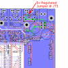
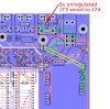
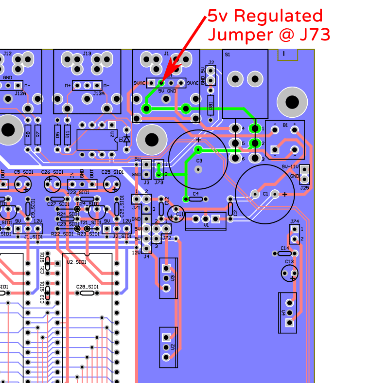
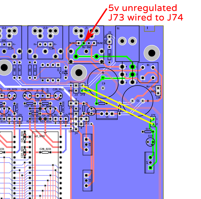
We definitely need to find a way to explain this better in the wiki - if anyone has any suggestions please post! Short answer: If your PSU generates regulated 5v, fit a jumper @ J73/connect pins 1 & 2 of J73 to each other. If your PSU generates unregulated 5v, wire J73:pin1 to J74:pin1 and wire J73:pin2 to J74:pin2. You will also need to fit C13, C14, and V4. Long answer: Regulated 5v input: The 5v rail comes in @ J1, routes through the power switch, then a jumper at J73 ties the 5v rail to all of the 5v traces on the board. 5v path=green: Unregulated 5v input: The 5v rail comes in @ J1, routes through the power switch, then a wire from J73:pin2 to J74:pin2 takes it through V4 to give regulated 5v at J74:pin1. A wire from J74:pin1 to J73:pin1 connects that regulated output from V4 to all of the 5v traces on the board. 5v path=green/wires=yellow: Best regards Tim