doc
-
Posts
1,079 -
Joined
-
Last visited
Never
Content Type
Profiles
Forums
Blogs
Gallery
Everything posted by doc
-
DIY audio patchbay with digital routing....How hard?
doc replied to Nomical's topic in Design Concepts
LOL. If I'll find someday the carton with the matrix in (and if my workspace is cleaned up...), I'll do all tests for you! ;D greets Doc -
DIY audio patchbay with digital routing....How hard?
doc replied to Nomical's topic in Design Concepts
I read it so far ;D Motorfader? You're joking. If someone wants his matrix with MF he should build another box. Not every project must handle every option. I think there isn't a mf-section in the MIDIO128, also. So go one without mf! :) greets Doc -
In rare cases, it can. But that doesn't matter in MTEs case. If the 100n are close to the regulators no problem may occur. One problem is the current. It makes the 9V regulator very hot. A good heatsink is a must. You can handle this, if you don't connect the 5V reg after the 9V. You can connect both Regulator-Inputs together and then take each voltage individual out. Then you have it seperated. In this case the 5V reg will get hot because of the high input voltage (which physical doesn't hurt the reg, because it can do 30V at the input. But the moreover voltage will be turned into heat). A good heatsink is a must here, also. Thats my opinion also. I've opened one C64 to have a look inside. It is a very simple, old circuit. The regulator used is a very old fashioned one (no wonder ... its 20 years old). Most broken psu I saw had contact problems around the fuses or bad solders. This psu is what it is: a 20+ year old brick! greets Doc
-
DIY audio patchbay with digital routing....How hard?
doc replied to Nomical's topic in Design Concepts
hehe Funny, how things go. What shall I do, that noone has the feeling to do something wrong? It is not worth the discussion. Everything is fine. So go on and let us build a matrix! ;D I never felt cut out of the loop. I just wanted to give several hints, how you can manage such a project. And. The matrix isn't my favourite project at the moment. Several Others are in cue now. I'll keep on with my suggestions and I also tell you when you run in the wrong direction, ok? You all rules! OK?! ;D greets Doc -
Nice to hear, that you've worked it out! hehe. That is the software we used to have before the great invention of MIOSstudio. ;D greets Doc
-
DIY audio patchbay with digital routing....How hard?
doc replied to Nomical's topic in Design Concepts
@screaming_rabbit Be glad you have it! I also saw the ready cable. But as I've seen the price, I shielded it by myself... @/tilted/ That was my thought. Not in a way that I felt ignored, or angry -That's absolutely not the case- but in a more funny way. If you read the whole thread as a non-involved you wake up thinking: " Hey! They are talking about constructing a new car ... and someone already drives along with it." greets Doc -
DIY audio patchbay with digital routing....How hard?
doc replied to Nomical's topic in Design Concepts
Just a hint about this: The DOCmatrix has shielded ribboncables. It's a little bit tricky to pack them into a alu-foil. But it's worth it. By doing the connections with multiple (shielded) rbbon cables you are saved from doing a three (ore more) layer PCB! greets Doc -
... and I also asume that you don't have a PIC18F4620, or? PICs from Smash have always MIOS on (they are tested before delivery from SmashTV). Tell us, which PIC you use. greets Doc
-
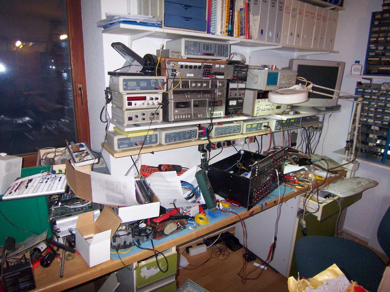
... as shown in the chat... a cleaned up mess.

-
DIY audio patchbay with digital routing....How hard?
doc replied to Nomical's topic in Design Concepts
...well... too much text to read it carefully... next time I'll read more ;D Doc -
DIY audio patchbay with digital routing....How hard?
doc replied to Nomical's topic in Design Concepts
ok, stryd ... Just to be sure you got it right. The DOCmatrix is a working box. It's not perfekt and I have to optimize some things. The "Group" can decide which chips they want. But that don't mean, the concept is wrong. My intention was never to go "alone". I had the idea and I've built it. Thats what I always do. If anyone wants to participate with this, everyone is welcome to do. Just for all: Here are the original schematics of the DOCmatrix. The Audio-Part: http://www.systemhaus-schneider.de/midibox/Audio%20in-out.pdf DIN matrix: http://www.systemhaus-schneider.de/midibox/DIN%20matrix.pdf DOUT matrix: http://www.systemhaus-schneider.de/midibox/DOUT%20matrix.pdf Line Driver (to extend the cable) http://www.systemhaus-schneider.de/midibox/linedriver.pdf Matrix digital: http://www.systemhaus-schneider.de/midibox/matrix%20digital.pdf Power Supply: http://www.systemhaus-schneider.de/midibox/power%20supply.pdf Shiftregister & Converter: http://www.systemhaus-schneider.de/midibox/Shift%20register%20and%20level%20converter.pdf Summing-Matrix: http://www.systemhaus-schneider.de/midibox/summing%20matrix.pdf So. This is the stuff you can discuss about. The software Thorsten has made run-ready but I didn't have the source (thats why he had the photos ... he he). As said before: This is a working 24x24 matrix. For the labels I have decided to put sticker next to the rows and lines. Thats enough for me. The only problem of this box is: If you switch the outputs together you have a loss of signal. 2 outs together is hearable. If you switch four together, you're in trouble. The crosstalk and the "audoiable" parameters are great for this box. I hope that this post now takes away "the miracle" of the DOCmatrix. It's just a box I've build (without to ask the "group"...) 8) ;D greets Doc -
Ja, so in etwa. Du kannst in einem extra Layer z.b. CCs auf eine Taste legen, die dann per Knopfdruck gesendet werden. Wenn Du es in Cubase machst (und nur da kann ich mitreden...) und jedes Instrument hat eine eigene Spur, dann würdest Du mit der LC die Spuren steuern. Andere Parameter eines VST-Instrumentes kannst Du entweder mit GPC Buttons steuern, oder mit einer extra Box. Ich kann mir es selber nicht so gut vorstellen, was Du genau vorhast bzw. ob es funktioniert.... Ich glaube fast, Du wirst die Software nicht brauchen, denn was die Midibox sendet, bestimmst Du! Der Midimerger ist bereits in den meisten Apps integriert. Ausnahme: Die MidiboxLC. Die LC benötigt zwingend einen eigenen, exclusiven MidiIn/MidiOut-Port, verbunden mit dem Host. Da kann man nichts mergen. Du bräuchtest als vermutlich 2 Boxen und 2 Midi-Interfaces. Doch, wirst Du! Denn dein Testcore kannst Du natürlich im Gesamtkonzept wieder verbauen. Da bleibt nix übrig. Ich kann dir stellenweise nur schwer folgen, müsste also auch erst anfangen zu coden um rauszufinden was geht und was nicht. Demnacht gilt hier: Der Weg ist das Ziel! greets Doc
-
Yes, indeed. I remember the time you were a noob, nILS ... ;D
-
Hi, Da liegst Du falsch ... Kuck dir mal die MidiboxLC an. Die macht nichts anderes als Mackie-Control... Das Problem dabei ist, daß Du in diesem Modus eben auf diesen Modus beschränkt bleibst. Einen Großteil deiner Wünsche könnte sicher mit einer LC realisiert werden.... Aber für das umschalten der VSTs in Cubase sehe ich eher schwarz. Mackie-Control ist eigentlich als Bedienoberfläche für hostbasierende DAWs gedacht (also eher ein Mischpult). Zum Glück kann man mit der MidiboxLC auch generische Kommandos senden (GPC-Controller). Das kann nicht mal das Original. Ausserdem besteht immer die Möglichkeit mehrere CORES mit unterschiedlichen Applikationen einzusetzen. Ich sehe Dein größeres Problem in der Auswahl der Software. Der Midibox-Part wäre jedoch, so wie du es darstellst, durchaus denkbar. Die Klaviatur würde ich aber nicht mit einer Midibox midifizieren. Das geht zwar, aber günstiger kommst Du sicherlich an ein ausgedientes Keyboard mit Midi-Schnittstelle ran, dass auch noch genug Platz für das Innenleben hat. Nun, für das Mackie Protokoll kannst Du dir irgendwo die Bedienungsanleitung saugen (www.mackie.com). Darin steht auch gleich, was geht und was nicht. Zum Einrichten generischer Controller musst Du wohl oder übel die Specs der jeweiligen Software studieren. Ich würde erstmal ein Core (und vielleicht ein DIN und ein DOUT) aufbauen. Damit kannst Du jederzeit die Applikation wechseln und verschiedene Software ausprobieren. Dieser Weg wäre überhaupt zunächst ratsam, damit Du besser in die Materie kommst und der "Frustfaktor" kontrollierbar bleibt. Generell kann ich mich nILS nur anschliesen: Auf die Bühne käme mir kein Rechner ... erst recht Keiner mit XP! Greets Doc
-
Hi Ilmenator, Nun, generell könnte ich alles über das Schalten von Netzspannung sagen. Ich möchte dies aber nicht hier veröffentlichen, da der Nachbau als Solcher für den Laien LEBENSGEFÄHRLICH ist. Durch die Box können theoretisch 400V und 75A fließen. Hier nur eine grobe Beschreibung. Den Rest (Schaltplan, Platinen, etc.) kann ich Dir gerne per PM zukommen lassen. Die Douts steuern über ULN Treiber die Relais. Die Relais schalten bei 12V. Am Ausgang kann jedes Relais 16/2500V schalten. Die Relaisspule hat noch eine Freilaufdiode. Die Schaltkontakte sind jeweils mit einem Funkenlöschkondensator versehen (10n/250V), damit auch "knackfrei" geschalten wird. Die Steuerspannung für die Relais (12V, max 1,8A) wird durch ein seperates Netzteil zur Verfügung gestellt. Ein Schlüsselschalter (in der 12V Leitung) schützt vor unbefugtem Einschalten der Verbraucher. Die 12V werden außerdem über eine Verzögerungsschaltung etwa erst 5 Sec nach dem Einschalten den Relais zur Verfügung gestellt. Dies war notwendig, da sonst unter bestimmten Umständen alle Relais beim Einschalten der Box kurz anziehen. Das wäre der Tod jeder Sicherung gewesen ... Die Verkabelung der Relais erfolgte (mit 2,5 btw 4 qmm Leitung) hinten auf Wago-Klemmen. Wichtig dabei sind vernünftige Sammelschienen für Erde und Nulleiter. Die einschlägigen Vorschriften zum Umgang mit Netzspannung sind hierbei unbedingt einzuhalten. So, das wars in Kürze. Ach ja: Die Platinen sollten auch VDE gerecht mit mindestens 6mm Leiterbahnen und genügend Abstand ausgestattet sein. Die Relais benötigen auch einen Mindestabstand von 7,5mm zueinander. Netzteile und Relais erzeugen Wärme. Eine zugriffgeschütze Luftzufuhr muss also auch gewährleistet sein. Noch mal meine Warnung: Ich helfe Jedem gerne, wenn er eine solche Unterverteilung bauen will. Es muß jedoch sichergestellt sein, das Jeder für sich weiß, was er tut, denn es geht hier um echte Ströme und diese können im Fall der Fälle, neben versicherungsrechtlichen Fragen, auch absolut lebensgefährlich tödlich sein. Gruss Doc
-
Lach! Kein Industriegebiet? Nur Arbeiter und Bauern? - Das hatten wir doch schonmal! :D ;D Gruss Doc
-
I Just don't understand, I should be getting signal!
doc replied to el_cuc0's topic in Testing/Troubleshooting
Ok. So you have MIOS on your PIC. But you need to upload an applikation via MIDI before you can use your Box. You will of course need a midi-In! greets Doc -
Hallo Thorsten, vielen Dank, dass Du mein Weltbild wieder gerade gerückt hast. Ich begann schon an mir zu zweifeln .... Ein Gutes hatte die Sache: Da mich dieser Fall nicht loslies und ich ihn auch nicht lösen könnte, habe ich endlich meinen C Schmöker ausm Regal geholt und angefangen, mir selber ne Applikation zu basteln (MTE hat mich ein wenig angeschubbst ...). Es funktioniert eigentlich schon alles und die PDU (Power Distribution Unit) kann ihre Arbeit aufnehmen. Ich werde aber die neue MIDIO128 trotzdem versuchen. Ach ja, Fotos gibts auch schon von meiner PDU oder Total Recall Controller... http://www.docstudios.de/pcu.htm Ach ja... Der Controller soll das gesamte Outboard-Equipment und die Beleuchtung steuern. Nicht nur über die Taster, sondern auch über Midi. Ich kann also jedem Cubase-Track sagen, welche Geräte er für den Song braucht und diese gleich automatisch einschalten lassen. In Zeiten teuerster Energie, ist dies auch ein Beitrag zum aktiven Strom-Sparen! ;D Vielen Dank nochmal, Thorsten (.. und MTE fürs anschubsen...) Gruss Doc
-
Sorry, to pick this up again and again ... (Yes, I miss it!) That was your best, twinny? 8) I mean: If I can't fix it, I destroy it? ;D I'm glad, I'm away this weekend. It would be nice, to see a full chat again, when I'm back ! greets Doc
-
I have one !! I found it again last year. I bought this in 1985 or so. I also had a midi-sequencer software for the C64. It rocked! ... But I wouldn't use it for today concepts anymore... greets Doc
-
-
Hey Twinny, ... after discussing this with MTE (no, not in the chat or the forum, because it's down...in icq) we both are the same oppinion: The forum and the chat runs on a C64 ! Please do a upgrade to C128 ..... Serious now: Whats up? Almost every evening and also in the morning the forum is very slow or it doesn't work at all. It's not funny anymore ... Are you still updating software, or whats up? Hope that we'll soon have our good,old, stable "newspaper" (hehe MTE) back. ;D greets Doc
-
Hi, ich habe seit gestern folgendes Problem: Ich habe eine MIDIbox MIDIO128, die ich vor ca. nem Jahr gebaut habe. Bis gestern funktionierte sie einwandfrei. Ich dachte, ein MIOS Update und die neueste Firmware können nicht schaden. Also draufgespielt. Ich habe 32 Taster und 32 LEDs (und Relais). Die Zuordnung ist 1:1. Hat ja bisher auch alles gepasst. Wenn ich die Relais viy Midi schalte, funktioniert alles. Wenn ich einen Taster drücke, kriege ich im Display den Korrkten Midi-Event angezeigt und der wird auch gesendet. Das zugehörige DOUT reagiert jedoch nicht mehr auf den Taster, sondern nur auf MIDI Events. Im der Main.asm ist: ; Forward Input to Output ; If 0: if an inputs gets an raising or falling edge, the appr. output ; pin will be set to the same new logic level. The output pin ; can be controlled via MIDI also ; If 1: an output pin can only controlled via MIDI #define DEFAULT_FORWARD_IO 0 Die midio128.ini: ################################################################################ # # This is an example init file for MIDIO128 # ################################################################################ ################################################################################ # File Type - allowed: midio128 ################################################################################ [TYPE] midio128 ################################################################################ # MIDI Merger: enable the merger in order to forward the incoming MIDI # events to the MIDI Out. A must if you would like to plug a keyboard # on the MIDI In, or if you want to cascade MIDIboxes # Allowed Keywords: # disabled don't use merger at all # enabled merges all external with internal events # mblink_fp MIDIbox Link Forwarding Point: like a common MIDI merger, # but internal events will be framed so that a MIDIbox Link # End Point can distinguish between a event which has been # sent by a common MIDI device and events which have been # generated by a MIDIbox # mblink_ep MIDIbox Link End Point: merges only external events # from a MBLink FP (Forwarding Point) ################################################################################ [MIDI_MERGER] enabled ################################################################################ # Debounce Time (in ms) # Increase this value if you notice jitter on the inputs # Decrease this value if you drive the input pins with logic # Allowed Values: 0-255 # Default: 20 (miliseconds) ################################################################################ [DEBOUNCE_TIME] 55 ################################################################################ # Enable Alternative Program Change Behaviour # If Disabled: on program change events, the appr. Output pin will # just toggle from logic 0 to logic 1 and vice versa # If Enabled: on program change events, all output pins of the same # channel will be set to logic 0, but the pin which is assigned # to the channel and to the program change value will be set # to logic 1 # Default: disabled ################################################################################ [ALT_PROGCHNG_BEHAVIOUR] enabled ################################################################################ # Forward Input to Output # If Enabled: if an inputs gets an raising or falling edge, the appr. output # pin will be set to the same new logic level. The output pin # can be controlled via MIDI also # If Disabled: an output pin can only controlled via MIDI # Default: disabled ################################################################################ [FORWARD_INPUT_TO_OUTPUT] enabled ################################################################################ # Inverse Inputs # If Disabled: Inputs are high active # If Enabled: Inputs are low actvive # Default: enabled (for MBHP DIN modules) ################################################################################ [INVERSE_INPUTS] enabled ################################################################################ # Inverse Outputs # If Disabled: Outputs are high active, reset value after poweron is "0" # If Enabled: Outputs are low active, reset value after poweron is "1" # Default: disabled ################################################################################ [INVERSE_OUTPUTS] disabled ################################################################################ # Touch Sensor Sensitivity # Allowed values: 1 - 32 # Default: 3 ################################################################################ [TOUCHSENSOR_SENSITIVITY] 3 ################################################################################ # The MIDI_IN and MIDI_OUT sections include all settings for the IO pins # ################################################################################ # Syntax for a MIDI IN entry (MIDI event controls output pin): # <pin-number> = <byte 0> <byte 1> # # The maximum allowed number of output pins is 128 # # Supported MIDI events (. stands for hex digit, vv stands for 00 or 7F) # 9. .. (Note On) Example: 90 30 (MIDIO128 receives 90 30 vv) # A. .. (Poly Aftertouch) Example: A0 30 (MIDIO128 receives A0 30 vv) # B. .. (Controller) Example: B0 07 (MIDIO128 receives B0 07 vv) # C. .. (Program Change) Example: C0 30 (MIDIbox receives C0 30) # D. .. (Channel Aftertouch) Example: D0 30 (MIDIbox receives D0 30) # E. .. (Pitch Bender) Example: E0 7F (MIDIbox receives E0 7F vv) # # - On 2-byte events (C. and D.), the output pins just toggle (0->1 or 1->0) ################################################################################ # Syntax for a MIDI OUT entry (input pin triggers MIDI event): # <pin-number> = <ON byte 0> <ON byte 1> <ON byte2> <OFF byte 0> <OFF byte 1> <OFF byte2> # # The maximum allowed number of input pins is 128 # # Supported MIDI events # (Note On) Example: 90 30 7F 90 30 00 @OnOff (ON: send 90 30 7F, OFF: send 90 30 00) # (Poly Aftertouch) Example: A0 30 7F A0 30 00 @OnOff (ON: send A0 30 7F, OFF: send A0 30 00) # (Controller) Example: B0 07 7F B0 07 00 @OnOff (ON: send B0 07 7F, OFF: send B0 07 00) # (Program Change) Example: C0 01 00 FF 00 00 @OnOff (ON: send C0 01, OFF: send nothing!) # (Channel Aftertouch) Example: D0 40 00 FF 00 00 @OnOff (ON: send D0 40, OFF: send nothing!) # (Pitch Bender) Example: E0 30 30 E0 60 60 @OnOff (ON: send E0 30 30, OFF: send E0 60 60) # # Also valid: # (Note On/Off) Example: 90 30 7F 80 30 00 @OnOff (ON: send 90 30 7F, OFF: send 80 30 00) # (Controller Fun) Example: B0 10 40 B0 11 40 @OnOff (ON: send B0 10 40, OFF: send B0 11 40) # # - If byte0 is FF, the event will not be sent # # Supported button behaviours (see MIDIbox tutorial): # @OnOff # @OnOnly # @Toggle # ################################################################################ [MIDI_IN] 1 = 90 30 2 = 90 31 3 = 90 32 4 = 90 33 5 = 90 34 6 = 90 35 7 = 90 36 8 = 90 37 9 = 90 38 10 = 90 39 11 = 90 3A 12 = 90 3B 13 = 90 3C 14 = 90 3D 15 = 90 3E 16 = 90 3F 17 = 90 40 18 = 90 41 19 = 90 42 20 = 90 43 21 = 90 44 22 = 90 45 23 = 90 46 24 = 90 47 25 = 90 48 26 = 90 49 27 = 90 4A 28 = 90 4B 29 = 90 4C 30 = 90 4D 31 = 90 4E 32 = 90 4F 33 = 90 50 34 = 90 51 35 = 90 52 36 = 90 53 37 = 90 54 38 = 90 55 39 = 90 56 40 = 90 57 41 = 90 58 42 = 90 59 43 = 90 5A 44 = 90 5B 45 = 90 5C 46 = 90 5D 47 = 90 5E 48 = 90 5F 49 = 90 60 50 = 90 61 51 = 90 62 52 = 90 63 53 = 90 64 54 = 90 65 55 = 90 66 56 = 90 67 57 = 90 68 58 = 90 69 59 = 90 6A 60 = 90 6B 61 = 90 6C 62 = 90 6D 63 = 90 6E 64 = 90 6F 65 = B0 10 66 = B0 11 67 = B0 12 68 = B0 13 69 = B0 14 70 = B0 15 71 = B0 16 72 = B0 17 73 = B0 18 74 = B0 19 75 = B0 1A 76 = B0 1B 77 = B0 1C 78 = B0 1D 79 = B0 1E 80 = B0 1F 81 = B0 20 82 = B0 21 83 = B0 22 84 = B0 23 85 = B0 24 86 = B0 25 87 = B0 26 88 = B0 27 89 = B0 28 90 = B0 29 91 = B0 2A 92 = B0 2B 93 = B0 2C 94 = B0 2D 95 = B0 2E 96 = B0 2F 97 = B0 30 98 = B0 31 99 = B0 32 100 = B0 33 101 = B0 34 102 = B0 35 103 = B0 36 104 = B0 37 105 = B0 38 106 = B0 39 107 = B0 3A 108 = B0 3B 109 = B0 3C 110 = B0 3D 111 = B0 3E 112 = B0 3F 113 = B0 40 114 = B0 41 115 = B0 42 116 = B0 43 117 = B0 44 118 = B0 45 119 = B0 46 120 = B0 47 121 = B0 48 122 = B0 49 123 = B0 4A 124 = B0 4B 125 = B0 4C 126 = B0 4D 127 = B0 4E 128 = B0 4F [MIDI_OUT] ########################################## # Pin # On Evnt # Off Evnt # Behaviour # ########################################## 1 = 90 30 7F 90 30 00 @Toggle 2 = 90 31 7F 90 31 00 @Toggle 3 = 90 32 7F 90 32 00 @Toggle 4 = 90 33 7F 90 33 00 @Toggle 5 = 90 34 7F 90 34 00 @Toggle 6 = 90 35 7F 90 35 00 @Toggle 7 = 90 36 7F 90 36 00 @Toggle 8 = 90 37 7F 90 37 00 @Toggle 9 = 90 38 7F 90 38 00 @Toggle 10 = 90 39 7F 90 39 00 @Toggle 11 = 90 3A 7F 90 3A 00 @Toggle 12 = 90 3B 7F 90 3B 00 @Toggle 13 = 90 3C 7F 90 3C 00 @Toggle 14 = 90 3D 7F 90 3D 00 @Toggle 15 = 90 3E 7F 90 3E 00 @Toggle 16 = 90 3F 7F 90 3F 00 @Toggle ########################################## # Pin # On Evnt # Off Evnt # Behaviour # ########################################## 17 = 90 40 7F 90 40 00 @Toggle 18 = 90 41 7F 90 41 00 @Toggle 19 = 90 42 7F 90 42 00 @Toggle 20 = 90 43 7F 90 43 00 @Toggle 21 = 90 44 7F 90 44 00 @Toggle 22 = 90 45 7F 90 45 00 @Toggle 23 = 90 46 7F 90 46 00 @Toggle 24 = 90 47 7F 90 47 00 @Toggle 25 = 90 48 7F 90 48 00 @Toggle 26 = 90 49 7F 90 49 00 @Toggle 27 = 90 4A 7F 90 4A 00 @Toggle 28 = 90 4B 7F 90 4B 00 @Toggle 29 = 90 4C 7F 90 4C 00 @Toggle 30 = 90 4D 7F 90 4D 00 @Toggle 31 = 90 4E 7F 90 4E 00 @Toggle 32 = 90 4F 7F 90 4F 00 @Toggle ########################################## # Pin # On Evnt # Off Evnt # Behaviour # ########################################## 33 = 90 50 7F 90 50 00 @OnOff 34 = 90 51 7F 90 51 00 @OnOff 35 = 90 52 7F 90 52 00 @OnOff 36 = 90 53 7F 90 53 00 @OnOff 37 = 90 54 7F 90 54 00 @OnOff 38 = 90 55 7F 90 55 00 @OnOff 39 = 90 56 7F 90 56 00 @OnOff 40 = 90 57 7F 90 57 00 @OnOff 41 = 90 58 7F 90 58 00 @OnOff 42 = 90 59 7F 90 59 00 @OnOff 43 = 90 5A 7F 90 5A 00 @OnOff 44 = 90 5B 7F 90 5B 00 @OnOff 45 = 90 5C 7F 90 5C 00 @OnOff 46 = 90 5D 7F 90 5D 00 @OnOff 47 = 90 5E 7F 90 5E 00 @OnOff 48 = 90 5F 7F 90 5F 00 @OnOff ########################################## # Pin # On Evnt # Off Evnt # Behaviour # ########################################## 49 = 90 60 7F 90 60 00 @OnOff 50 = 90 61 7F 90 61 00 @OnOff 51 = 90 62 7F 90 62 00 @OnOff 52 = 90 63 7F 90 63 00 @OnOff 53 = 90 64 7F 90 64 00 @OnOff 54 = 90 65 7F 90 65 00 @OnOff 55 = 90 66 7F 90 66 00 @OnOff 56 = 90 67 7F 90 67 00 @OnOff 57 = 90 68 7F 90 68 00 @OnOff 58 = 90 69 7F 90 69 00 @OnOff 59 = 90 6A 7F 90 6A 00 @OnOff 60 = 90 6B 7F 90 6B 00 @OnOff 61 = 90 6C 7F 90 6C 00 @OnOff 62 = 90 6D 7F 90 6D 00 @OnOff 63 = 90 6E 7F 90 6E 00 @OnOff 64 = 90 6F 7F 90 6F 00 @OnOff ########################################## # Pin # On Evnt # Off Evnt # Behaviour # ########################################## 65 = B0 10 7F B0 10 00 @OnOff 66 = B0 11 7F B0 11 00 @OnOff 67 = B0 12 7F B0 12 00 @OnOff 68 = B0 13 7F B0 13 00 @OnOff 69 = B0 14 7F B0 14 00 @OnOff 70 = B0 15 7F B0 15 00 @OnOff 71 = B0 16 7F B0 16 00 @OnOff 72 = B0 17 7F B0 17 00 @OnOff 73 = B0 18 7F B0 18 00 @OnOff 74 = B0 19 7F B0 19 00 @OnOff 75 = B0 1A 7F B0 1A 00 @OnOff 76 = B0 1B 7F B0 1B 00 @OnOff 77 = B0 1C 7F B0 1C 00 @OnOff 78 = B0 1D 7F B0 1D 00 @OnOff 79 = B0 1E 7F B0 1E 00 @OnOff 80 = B0 1F 7F B0 1F 00 @OnOff ########################################## # Pin # On Evnt # Off Evnt # Behaviour # ########################################## 81 = B0 20 7F B0 20 00 @OnOff 82 = B0 21 7F B0 21 00 @OnOff 83 = B0 22 7F B0 22 00 @OnOff 84 = B0 23 7F B0 23 00 @OnOff 85 = B0 24 7F B0 24 00 @OnOff 86 = B0 25 7F B0 25 00 @OnOff 87 = B0 26 7F B0 26 00 @OnOff 88 = B0 27 7F B0 27 00 @OnOff 89 = B0 28 7F B0 28 00 @OnOff 90 = B0 29 7F B0 29 00 @OnOff 91 = B0 2A 7F B0 2A 00 @OnOff 92 = B0 2B 7F B0 2B 00 @OnOff 93 = B0 2C 7F B0 2C 00 @OnOff 94 = B0 2D 7F B0 2D 00 @OnOff 95 = B0 2E 7F B0 2E 00 @OnOff 96 = B0 2F 7F B0 2F 00 @OnOff ########################################## # Pin # On Evnt # Off Evnt # Behaviour # ########################################## 97 = B0 30 7F B0 30 00 @OnOff 98 = B0 31 7F B0 31 00 @OnOff 99 = B0 32 7F B0 32 00 @OnOff 100 = B0 33 7F B0 33 00 @OnOff 101 = B0 34 7F B0 34 00 @OnOff 102 = B0 35 7F B0 35 00 @OnOff 103 = B0 36 7F B0 36 00 @OnOff 104 = B0 37 7F B0 37 00 @OnOff 105 = B0 38 7F B0 38 00 @OnOff 106 = B0 39 7F B0 39 00 @OnOff 107 = B0 3A 7F B0 3A 00 @OnOff 108 = B0 3B 7F B0 3B 00 @OnOff 109 = B0 3C 7F B0 3C 00 @OnOff 110 = B0 3D 7F B0 3D 00 @OnOff 111 = B0 3E 7F B0 3E 00 @OnOff 112 = B0 3F 7F B0 3F 00 @OnOff ########################################## # Pin # On Evnt # Off Evnt # Behaviour # ########################################## 113 = B0 40 7F B0 40 00 @OnOff 114 = B0 41 7F B0 41 00 @OnOff 115 = B0 42 7F B0 42 00 @OnOff 116 = B0 43 7F B0 43 00 @OnOff 117 = B0 44 7F B0 44 00 @OnOff 118 = B0 45 7F B0 45 00 @OnOff 119 = B0 46 7F B0 46 00 @OnOff 120 = B0 47 7F B0 47 00 @OnOff 121 = B0 48 7F B0 48 00 @OnOff 122 = B0 49 7F B0 49 00 @OnOff 123 = B0 4A 7F B0 4A 00 @OnOff 124 = B0 4B 7F B0 4B 00 @OnOff 125 = B0 4C 7F B0 4C 00 @OnOff 126 = B0 4D 7F B0 4D 00 @OnOff 127 = B0 4E 7F B0 4E 00 @OnOff 128 = B0 4F 7F B0 4F 00 @OnOff Was ist passiert? Entweder ich krieg Alsheimer oder es hat sich irgendwas an der Software geändert... Wenn ich die AIN_DIN_etc Testapp lade, kann ich die LEDs und die Relais einwandfrei über die Taster ansprechen. Hardwarefehler somit ausgeschlossen. Hilfe! Gruss Doc
-
Biggest MTC-Display ... or MIDIBOXes the world don't need?
doc replied to doc's topic in Design Concepts
Nicht der Beste ... Der SCHÖNSTE! ;D ;D -
Biggest MTC-Display ... or MIDIBOXes the world don't need?
doc replied to doc's topic in Design Concepts
Hey! Thats a good idea. I will implement this. Thanks