julienvoirin
-
Posts
790 -
Joined
-
Last visited
-
Days Won
3
Content Type
Profiles
Forums
Blogs
Gallery
Everything posted by julienvoirin
-

Connecting a MIDI DIN port directly to digital logic?
julienvoirin replied to laserbeak43's topic in Parts Questions
yes it is OK the optocoupleur at IN is done to avoid that a short circuit on device N-1 (e.g a synth plugged on 220V) destroy device N (e.g a rack module) using gates 7400 isn't necessary in OUT ; but like this you are sure that the TTL signal will be perfect. if you are gready you can directly connect Tx bus of device N-1 to Rx bus of device N (but there is no more short circuuit protection) -
btw you don't have to use 7pin DIN connector : only 4 pin DIN is necessary if it is cheaper. remember, you do your own connector avoid 5 DIN for the supply as you could plug it in MIDI ports hazardly
-
yes ribbon cable, sorry french abuse Commodore supply : 1 pin is +5V, another is ground, the 2 others deliver 12V AC (from memory) design the circuit on your board like on this schematic : http://www.ucapps.de/mbhp/mbhp_8xsid_c64_psu_optimized.pdf If you do not have one, just get a 9V DC PSU and use a common ground for 5V and 9V regulator. Derive the tension of the 5V regulator AFTER the 9V regulator. Be carefull, the 7805 will be rather hot as it must eliminate a lot of energy (9V->5V drop). In this case, only one 2200uF and 330nF but two 100uF and 100n for the power switch find DPST (double pole = bipolar = 2x3 pins under the switch)
-
just an advice (from a confirmed amateur midiboxer) : get a cheap multimeter (10 bucks, numerical display) to check you have the right voltages to avoid frying your so rare SID chipsets (and the PIC too as it is preprogrammed) it will also be very useful to debug, most errors being a bad/wrong soldering between +5V lines and the ground. To know if there is a short between 2 points (or lines) put the multimeter in "bipbip" mode or DIODE mode (it displays something like 001 is there is connection, error if not) test all your voltages before stuffing the IC (PIC, SID, 74HC165, 74HC595). if it is OK, plug them and everything should work. Get coloured flat cable too, it helps a lot to better understand what points are connected together (instead of grey one)
-
le mieux serait de tester les assignations de LED à l'aide du clavier de MIOS studio (ou d'un clavier midi capable d'envoyer une à une les 128 notes midi de la norme et de l'appli 64ain128din128dout (mais il te faut un Core 8 bit dans ce cas). Cette appli est super pratique, je m'en sers bcp pour vérifier mes connections et repérer mes numéros de boutons/led sans avoir à me poser trop de question au montage/soudure avant de développer des petites applications (je fais déjà le hard sans me demander où est connecté chq bouton, ensuite je repere le numéro grâce a ce petit truc, puis je code un fichier define.h - c'est vachement plus simple et plus modulaire). EDIT : oups, some french in général forum :blush: I know the guy
-
tu es sur de ton coup ? si tu as suivi le schema de base il me semble que ce devrait être 0 pour la première ligne : chaque bouton est connecté à une seule et unique pin de DIN, idem LED mais DOUT de même si tu as suivi le schéma de base, sans SD card, tout est supposé fonctionner. seuls les "presets" de pattern n'existent pas (y a pas de stockage, normal, y a juste le buffer de l'appli)
-
mets m'en un de coté selim j'vais recevoir une CS PCB d'ici qlq jours des news de mon panneau de M1000 controller ? ++
-
you are welcome :thumbsup:
-
1st LCD, section 2.1 Vcc-Vee = 23 if Vcc = +5V then that means that Vee is negative (remember some maths) Vee sets the contrast Section 3.2 : typical LCD Driving voltage : Vcc-Vee = +13V I let you solve this very complicated equation at 3rd degree. Your contrast is driven by a negative voltage. provide a source of -18V, DC 2nd LCD use the circuitry of the core to control it. it is a classical CLCD (toshiba driver). just use a 20K trimmer for contrast instead of 10K
-
"Super red"/"Hyper red" LEDs for MB6582 control surface?
julienvoirin replied to Hawkeye's topic in Parts Questions
i agree with futureman just get classic diffused 3mm red LED (Reichelt does them for cheap) -
sequencer v2.4 (or V1, don't remember, it was 5 years ago) based on MB64. but not sure it supports AOUTi've checked, it supports. but it is a bit complicated you should seriously think to seqV4, it has amazing features which make it play alone, you don't need to enter complicated sequence, it is enough smart to play music without human ! another advantage : encoders allow total recall and just to argument : V4 supports AOUT on 8CV+8gates very well. config can be memorised, you can name your outputs with the corresponding parameters of your modular for example. store your studio setup config, etc ... you can also add 64 trigger outputs for an analog drum machine V4 is controllable by USB through your computer. have a look at BLM16*16, it is amazing
-
check the 4bits wiring
-
interesting is it hosted by radio spares ?
-
PM sent :ahappy:
-
 the "holes" are 3mm holes to fix the braces/spacers (threaded holes like on the back of Wilba sequencer panel) : how do you fix the veroboard or PCB on it ??
 -
excellent ! where did you get this silkscreen done ? how do you do blind holes on the inner side ?
-
really really nice i've been hesitating to get one for a custom matrix1000 controller and finally used mini 4x20 classic clcd but vfd are really expensive the best will be to put a brown plastic screen in front of it to get the 80's style like on oberheim expander
-
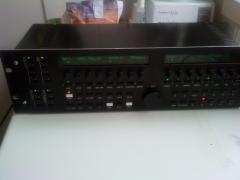
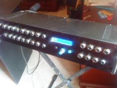
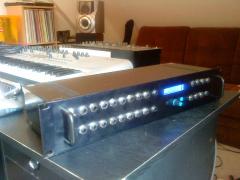
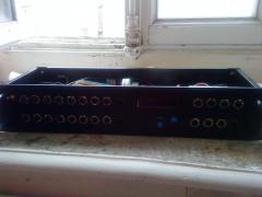
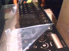
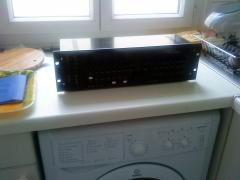
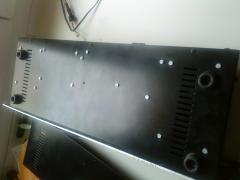
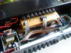
various midibox pictures
-
-
From the album: julienvoirin pics
-
From the album: julienvoirin pics
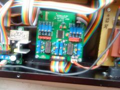
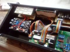
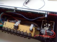
clean isn't it ? -
From the album: julienvoirin pics
5€ ELPAC GR-114B PSU (+/-12V 250mA ; +5V 1A) @Selectronic.fr Handmade Gate and CV veroboard PCB Handmade I2C + SDCard/Eth veroboard PCB Modded to output 5V gates with 3.3V from the Core32© © J.Voirin 2010
-
From the album: julienvoirin pics
-
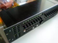
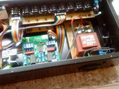
From the album: julienvoirin pics
© © J.Voirin 2010
-
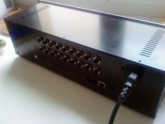
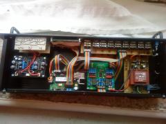
From the album: julienvoirin pics
8 Gates out 8 CV out 1 Clock out 1 Run/Stop out USB 4 I2C out 2x2 MIDI i/o Ethernet SD Card Sync24 out 220V AC powered Rack hand drilled (long and complicated)