julienvoirin
-
Posts
790 -
Joined
-
Last visited
-
Days Won
3
Content Type
Profiles
Forums
Blogs
Gallery
Everything posted by julienvoirin
-
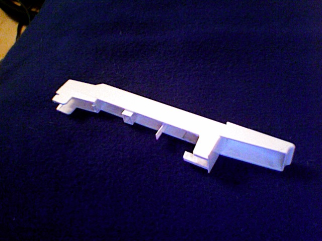
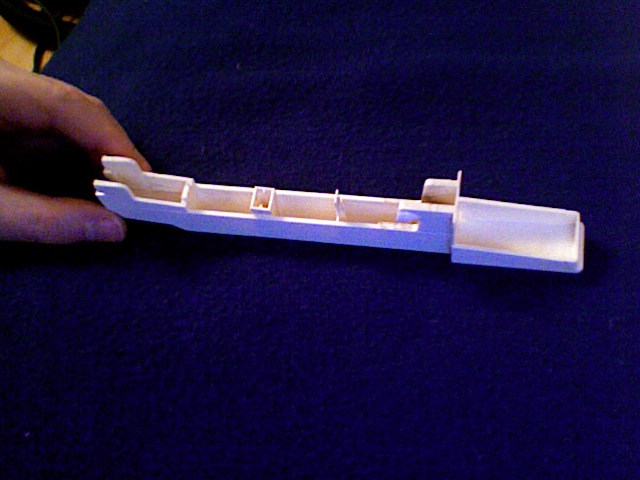
dear midiboxers i am looking for oberheim matrix6 keys ; E and D any infos are welcome of course see picture for infos best regards


-

40x2 Green-on-Black Optrex Displays - ORDERING INSTRUCTIONS
julienvoirin replied to fussylizard's topic in Bulk Orders
items received : thanks :) super well packed !!! -
a midibox 64 or other? to replace a too much expensive roland mpg 80
julienvoirin replied to boops's topic in Design Concepts
I can help you out, I've thought to the same device for a Matrix 1000 programmer :P exemple : ///////////////////////////////////////////////////////////////////////////// // This function is called by MIOS when an button has been toggled // pin_value is 1 when button released, and 0 when button pressed ///////////////////////////////////////////////////////////////////////////// void DIN_NotifyToggle(unsigned char pin, unsigned char pin_value) __wparam { #if 1 // only for debugging - remove this (or change "#if 1" to "#if 0") in a common application! DEBUG_MSG_SendHeader(); DEBUG_MSG_SendCString("Button: "); DEBUG_MSG_SendBCD3(pin); DEBUG_MSG_SendChar(' '); DEBUG_MSG_SendCString(pin_value ? "depressed" : "pressed"); DEBUG_MSG_SendFooter(); #endif // a button has been pressed, send Note at channel 1 MIOS_MIDI_BeginStream(); MIOS_MIDI_TxBufferPut(0x90); // Note at channel 1 MIOS_MIDI_TxBufferPut(pin); // pin number corresponds to note number MIOS_MIDI_TxBufferPut(pin_value ? 0x00 : 0x7f); // buttons are high-active MIOS_MIDI_EndStream(); case 0 : if (pin-value = 0){ MIOS_MIDI_TxBufferPut(message SysEx); // et allumage de Led : MIOS_DOUT_PinSet(unsigned char pin, unsigned char value); }else{ faire une truc} } case 1 : etc .. ///////////////////////////////////////////////////////////////////////////// // This function is called by MIOS when an encoder has been moved // incrementer is positive when encoder has been turned clockwise, else // it is negative ///////////////////////////////////////////////////////////////////////////// void ENC_NotifyChange(unsigned char encoder, char incrementer) __wparam { } ///////////////////////////////////////////////////////////////////////////// // This function is called by MIOS when a pot has been moved ///////////////////////////////////////////////////////////////////////////// void AIN_NotifyChange(unsigned char pin, unsigned int pin_value) __wparam { switch (pin) { MIOS_MIDI_BeginStream(); case 0 : //potard 0, soit AIN1 pin0 // a pot has been moved, send CC# or SySex<pin-number> at channel 1 MIOS_MIDI_TxBufferPut(0xb0); // CC at channel 1 MIOS_MIDI_TxBufferPut(0x00); // pin number corresponds to CC number MIOS_MIDI_TxBufferPut(pin_value); or MIOS_MIDI_TxBufferPut(message sysex + pin_value)); // don't send 10bit pin_value, but 7bit value case 1 : etc .... MIOS_MIDI_EndStream(); // notify display handler in DISPLAY_Tick() that AIN value has changed last_ain_pin = pin; app_flags.DISPLAY_UPDATE_REQ = 1; } -
Dear All I've tried the GLCD option with MIOS32. The model is JM12864E and JM12864J. Its driver should be KS0108 from the datasheet. http://www.hzkcgd.com/pdf/JM12864E.pdf In Mac Os terminal, i've compiled the app_LCD tutorial , using the command line export MIOS328LCD=ks0108 make-s Unfortunatly, the display is not good: only the half left of the display displays something and what is displayed is a mix between the left and right of what is expected on the screen (a gauge modulated by modwheel). The 000 value column is centered CS 1 and 2 of the display are connected to J5C (A8 & A9 pins respectively) http://www.ucapps.de/mbhp/mbhp_lcd_ks0108_mios32.pdf In the Module code : CS1 is relative to CS0 and CS2 to CS1 (code starts at 0, datasheet starts at 1) J15 is well cabled as I have a picture ; while uploading firmware, It writes "MIO oader" (insted of "mios bootloader") Does someone have an idea of what I should do to configure it correctly ? I've updated my svn repository to the last changes (today) of course. I think it is a problem in the column driver or the CS config ; isn't it ? :( Thanks in advance
-
i shared the code if i remember for a 8x6 matrix keyboard (the code has been done for reboot) http://4colors.free.fr/midibox/mes_projets/matrix%208x6%20keyboard_c_49_kbd_v3/
-
Dear Midiboxers I've made a Bipolar PSU 220V AC : +/- 12V DC, following those rules : =bipolar&s[]=psu]http://www.midibox.org/dokuwiki/doku.php?id=bipolar_12v_psu&s[]=bipolar&s[]=psu It works fine, i've done it on verobaord with Fuse and switch, but i'd like to protect the user (me !) against electric shocks as it will be handled and used as is (not in a box). I've already put some nails enamel on the 220V circuit before the transformer and i would like to know if it is efficient (and enough !) Any advices welcome :)
-
MB-SEQ V3/V4 Control Surface PCB and matching case
julienvoirin replied to Wilba's topic in MIDIbox SEQ
don't do this, there is the config file to customize :o -
MB-SEQ V3/V4 Control Surface PCB and matching case
julienvoirin replied to Wilba's topic in MIDIbox SEQ
solder it on veroboard with an additional DIL and put it in the bottom of the enclosure. another solution is to use a straight floppy connector on a vero and screw the vero on the panel. (or more gribish : the floppy connector of the C64 !) HE 902 : http://www.electronique-diffusion.fr/product_info.php?cPath=23_412_445&products_id=10921 -
MB-SEQ V3/V4 Control Surface PCB and matching case
julienvoirin replied to Wilba's topic in MIDIbox SEQ
bought mine at : http://cgi.ebay.fr/SD-card-module_W0QQitemZ380094512121QQcmdZViewItemQQptZLH_DefaultDomain_0?hash=item587f65fbf9&_trksid=p3911.c0.m14#ht_2627wt_1242 works well -
MB-SEQ V3/V4 Control Surface PCB and matching case
julienvoirin replied to Wilba's topic in MIDIbox SEQ
to TwinX : i have job for you ! I need a "panel" for my Rainbow I am in ! I need ONE please -
MB-SEQ V3/V4 Control Surface PCB and matching case
julienvoirin replied to Wilba's topic in MIDIbox SEQ
:o :o :o :oU R so DIRTY -
live api - anybody successful with it?
julienvoirin replied to ultra's topic in MIOS programming (C)
please edit WIKI :) i am very interested to implement it in my Rainbow STM32 RGB buttons led controller -
No, SRIO = 74HC165 (i've just verified in the mios functions explanation), not pin of each SRIO. 16 is the maximum which correponds to 4 x DINX4. Thnaks btw
-
DINx4 has been tested with miodio128 and is fully working. By swapping encoders on the 74HC165, it shows that my building is working too. So it is only software. Help please :-[
-
here is the code : /* #include "cmios.h" #include "pic18f452.h" // absolute values are stored in this array unsigned char enc_value[16]; ///////////////////////////////////////////////////////////////////////////// // This function is called by MIOS after startup to initialize the // application ///////////////////////////////////////////////////////////////////////////// void Init(void) __wparam { unsigned char i; // set shift register update frequency MIOS_SRIO_UpdateFrqSet(1); // ms // we need to set at least one IO shift register pair MIOS_SRIO_NumberSet(16); // for 128 pins // set speed mode for 16 encoders for(i=0; i<16; ++i) { // available speed modes: SLOW, NORMAL and FAST MIOS_ENC_SpeedSet(i, MIOS_ENC_SPEED_SLOW, 2); // encoder, speed mode, divider } } ///////////////////////////////////////////////////////////////////////////// // This function is called by MIOS in the mainloop when nothing else is to do ///////////////////////////////////////////////////////////////////////////// void Tick(void) __wparam { } ///////////////////////////////////////////////////////////////////////////// // This function is periodically called by MIOS. The frequency has to be // initialized with MIOS_Timer_Set ///////////////////////////////////////////////////////////////////////////// void Timer(void) __wparam { } ///////////////////////////////////////////////////////////////////////////// // This function is called by MIOS when the display content should be // initialized. Thats the case during startup and after a temporary message // has been printed on the screen ///////////////////////////////////////////////////////////////////////////// void DISPLAY_Init(void) __wparam { MIOS_LCD_Clear(); MIOS_LCD_CursorSet(0x00); MIOS_LCD_PrintCString("Hello World!"); } ///////////////////////////////////////////////////////////////////////////// // This function is called in the mainloop when no temporary message is shown // on screen. Print the realtime messages here ///////////////////////////////////////////////////////////////////////////// void DISPLAY_Tick(void) __wparam { } ///////////////////////////////////////////////////////////////////////////// // This function is called by MIOS when a complete MIDI event has been received ///////////////////////////////////////////////////////////////////////////// void MPROC_NotifyReceivedEvnt(unsigned char evnt0, unsigned char evnt1, unsigned char evnt2) __wparam { } ///////////////////////////////////////////////////////////////////////////// // This function is called by MIOS when a MIDI event has been received // which has been specified in the MIOS_MPROC_EVENT_TABLE ///////////////////////////////////////////////////////////////////////////// void MPROC_NotifyFoundEvent(unsigned entry, unsigned char evnt0, unsigned char evnt1, unsigned char evnt2) __wparam { } ///////////////////////////////////////////////////////////////////////////// // This function is called by MIOS when a MIDI event has not been completly // received within 2 seconds ///////////////////////////////////////////////////////////////////////////// void MPROC_NotifyTimeout(void) __wparam { } ///////////////////////////////////////////////////////////////////////////// // This function is called by MIOS when a MIDI byte has been received ///////////////////////////////////////////////////////////////////////////// void MPROC_NotifyReceivedByte(unsigned char byte) __wparam { } ///////////////////////////////////////////////////////////////////////////// // This function is called by MIOS before the shift register are loaded ///////////////////////////////////////////////////////////////////////////// void SR_Service_Prepare(void) __wparam { } ///////////////////////////////////////////////////////////////////////////// // This function is called by MIOS after the shift register have been loaded ///////////////////////////////////////////////////////////////////////////// void SR_Service_Finish(void) __wparam { } ///////////////////////////////////////////////////////////////////////////// // This function is called by MIOS when an button has been toggled // pin_value is 1 when button released, and 0 when button pressed ///////////////////////////////////////////////////////////////////////////// void DIN_NotifyToggle(unsigned char pin, unsigned char pin_value) __wparam { } ///////////////////////////////////////////////////////////////////////////// // This function is called by MIOS when an encoder has been moved // incrementer is positive when encoder has been turned clockwise, else // it is negative ///////////////////////////////////////////////////////////////////////////// void ENC_NotifyChange(unsigned char encoder, char incrementer) __wparam { unsigned char new_value; // do nothing if encoder number greater than array size if( encoder >= sizeof(enc_value) ) return; // add incrementer to absolute value, store result in new_value new_value = enc_value[encoder] + incrementer; // branch depending on direction if( incrementer >= 0 ) { // overrun check: if new value >= 0x80, force to 0x7f (127) if( new_value >= 0x80 ) new_value = 0x7f; } else { // underrun check: if new value >= 0x80, force to 0x00 (0) if( new_value >= 0x80 ) new_value = 0x00; } // store and send absolute value if it has been changed if( new_value != enc_value[encoder] ) { enc_value[encoder] = new_value; MIOS_MIDI_TxBufferPut(0xb0); // CC at MIDI Channel #1 MIOS_MIDI_TxBufferPut(0x10 + encoder); // CC# is 0x10 (16) for first encoder MIOS_MIDI_TxBufferPut(new_value); } } ///////////////////////////////////////////////////////////////////////////// // This function is called by MIOS when a pot has been moved ///////////////////////////////////////////////////////////////////////////// void AIN_NotifyChange(unsigned char pin, unsigned int pin_value) __wparam { } and i modified the mios.table.inc as this : extract ;; encoder entry structure ENC_ENTRY MACRO sr, din_0, mode dw (mode << 8) | (din_0 + 8*(sr-1)) ENDM ENC_EOT MACRO dw 0xffff ENDM global _MIOS_ENC_PIN_TABLE _MIOS_ENC_PIN_TABLE MIOS_ENC_PIN_TABLE ;; SR Pin Mode ENC_ENTRY 1, 0, MIOS_ENC_MODE_DETENTED2 ; V-Pot 1 ENC_ENTRY 1, 2, MIOS_ENC_MODE_DETENTED2 ; V-Pot 2 ENC_ENTRY 1, 4, MIOS_ENC_MODE_DETENTED2 ; V-Pot 3 ENC_ENTRY 1, 6, MIOS_ENC_MODE_DETENTED2 ; V-Pot 4 ENC_ENTRY 2, 0, MIOS_ENC_MODE_DETENTED2 ; V-Pot 5 ENC_ENTRY 2, 2, MIOS_ENC_MODE_DETENTED2 ; V-Pot 6 ENC_ENTRY 2, 4, MIOS_ENC_MODE_DETENTED2 ; V-Pot 7 ENC_ENTRY 2, 6, MIOS_ENC_MODE_DETENTED2 ; V-Pot 8 ENC_ENTRY 3, 0, MIOS_ENC_MODE_DETENTED2 ; V-Pot 9 ENC_ENTRY 3, 2, MIOS_ENC_MODE_DETENTED2 ; V-Pot 10 ENC_ENTRY 3, 4, MIOS_ENC_MODE_DETENTED2 ; V-Pot 11 ENC_ENTRY 3, 6, MIOS_ENC_MODE_DETENTED2 ; V-Pot 12 ENC_ENTRY 4, 0, MIOS_ENC_MODE_DETENTED2 ; V-Pot 13 ENC_ENTRY 4, 2, MIOS_ENC_MODE_DETENTED2 ; V-Pot 14 ENC_ENTRY 4, 4, MIOS_ENC_MODE_DETENTED2 ; V-Pot 15 ENC_ENTRY 4, 6, MIOS_ENC_MODE_DETENTED2 ; V-Pot 16 ;; encoders 17-32 ENC_EOT ENC_EOT ENC_EOT and it doesn't work for encoder 9 to 16 ! why ??
-
MB-SEQ V3/V4 Control Surface PCB and matching case
julienvoirin replied to Wilba's topic in MIDIbox SEQ
after testing the resistance to weight of my monome's frontpanel, i think that Alu 3-4mm is better for frontpanel. Moreover the height of the spacer and encoder won't allow a 6-7 mm acryl frontpanel (the sandwich height with 2 acryl panels). But the case can be acryl ;) -
MB-SEQ V3/V4 Control Surface PCB and matching case
julienvoirin replied to Wilba's topic in MIDIbox SEQ
he use a sandwich technique with 2 acryl panels. the lower one has holes, screw and spacers. In black satin you see no screw behind the upper panel ;) it's a bit like threated holes from schaeffer if you cut the panel in 2 thicker ones. it is very clever and very cheap to do ! his tonon + mortaise technique for the case is very good too. yeah as i did on SEQ_2U (dédicace à reboot) -
MB-SEQ V3/V4 Control Surface PCB and matching case
julienvoirin replied to Wilba's topic in MIDIbox SEQ
Wilba does only PCB ! he recommends Schaeffer for panel. -
MB-SEQ V3/V4 Control Surface PCB and matching case
julienvoirin replied to Wilba's topic in MIDIbox SEQ
machinecollective.org (xndr) could maybe build our panel and case in black satin acryl ? i ordered him a monome 40h top and bottom and the quality is just PERFECT ! btw is there dxf of the panel ?? -
I would try sparkfun's one, there are rather big (1,2cmx1,2cm);and can make visual feedback with LED http://www.sparkfun.com/commerce/product_info.php?products_id=7835 USB version is ready to go to a computer but you nedd to write the prog you can cut unneccesary buttons from the PCB (4x6 is easier to make)
-
MB-SEQ V3/V4 Control Surface PCB and matching case
julienvoirin replied to Wilba's topic in MIDIbox SEQ
I'd like one please. I only know the wiki page order but no list -
TheRainbow - Midibox and RGB Led Keyboard
julienvoirin replied to julienvoirin's topic in MIDIbox User Projects
http://lennonluks.atspace.com/projects/senior_project/senior_project.htmli like it :) -
Dear All does anyone have tried to extend sm64 to 128 ? according to the code, it seems that we count from 0 to 7 for the rows in the .inc ; I have been thinking to count from 0 to 15 in order to get 128 button/leds. Is it the idea ? More to come
-
ah putain ! t'as les photos il me les faut avec le synthé allumé :)
-
i would use button duoled matrix app if i were you and customize the app writing your own app. this allow you to have 64x2 Digital outputs and 64 Digital input. the 64 first dout would allow you to use led to see which frame is "ON" and the second 64 DOUT would be sent to relays. you will only use 2 74HC165 and 4 74HC595, one core and one bankstick. very cheap. the only problem you will have is to write the application in order to store the patches. http://www.midibox.org/forum/index.php/topic,10476.msg79411.html http://www.midibox.org/forum/index.php/topic,12724.0.html