rosch
-
Posts
705 -
Joined
-
Last visited
-
Days Won
1
Content Type
Profiles
Forums
Blogs
Gallery
Everything posted by rosch
-
anyone interested? i have a 8580 and would like to trade it for a 6581. it's pulled & tested, everything fine. pm if you like!
-
i must say i'm not at all sure about my soldering. there could have been a problem from the very beginning which i just haven't noticed. anyway, no hurry here! thanks!
-
could be i was wrong with successfully uploading the sid firmware, it might also have been an assumption, after all (as the previous application still existed) today i tried to upload midibox 64 and midio 128 firmwares to 2 pic18F452 i just burned the bootloader on. the connection is there, the pic 18F is recognized and when i upload the firmware it seems to work. after it's finished mios2 says "waiting for reboot", but the reboot never happens. then it reports "bootloader up & running" again so the gm5x5x5 seems to work, and not to work, at the same time... i'll hook that sucker to a scope and see if i can find anything.
-
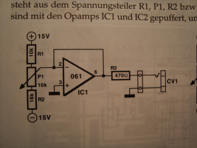
that would be a cv source. the one in the pic is balanced and buffered. the cutoff needs bipolar cv, while the resonance gets positive voltage. if it's not standalone you could omit the opamp. i'm no expert so i might be incorrect, or missing something, or different values (?) the pic is from the formant book.
-
thank you, TK! ok here we go: without jumper i have always connection from O4 to I1 (i checked them all) with jumper there's following connections: O5-I5 O4-I1 with cable these connections (no jumper): O1-I2, I3 O2-I2, I3 O3-I2, I3 O4-I1, I2, I3 O5-I2, I3 (i checked all outs with every in) all midi loops were sending and receiving the long strings correctly. so i hooked the MBSidV2 to the O3 and I3 and managed to upload the previously working firmware (with the previously working LCD) and it was also detected by MIOS Studio. thanks a lot so far, but seems like there's quite a mess on my board one thing i maybe should mention is the upload didn't start automatically after powering the sid. instead the application booted normally, then i started the transfer and that worked.
-
i actually like the way you sing. it just sounds way more ambient than the rest of the recording. also there's some level changes/volume modulations that seem a bit strange when listening. but the singing itself is cool. that effort has already been made by Herbert Grönemeyer!
-
i don't have another interface at hand. and very unfortunately i can't find my other 2 gm5 chips anymore, while i have two empty gm5x5x5 boards. i've tested it with the Shruthi-1, normal midi play works fine, via Klee sequencer for example. also the brand new Shruthi-1 editor (windows) works in terms of sending CC-messages for synthesis parameter, but i can't send a patch to the synth. midi in of the gm5 also doesn't work from Shruthi. sending firmware to that synth worked, with elektron C6 application. i've changed the old 2x20 immediately and tried again. there were no random symbols anymore, and no noise, although the pic18F4685 still carries the 4-lines modification in the firmware, as i haven't been able to upload the old file, at least the normal way. i can try that again without handshake, maybe that works. i'll also compare the core with another one, with regard to voltages. i guess there's something wrong, as i do not think a (maybe false or insufficient) lcd declaration in the firmware should have effect on midi out, or even interfaces, idk thanks for the input! any ideas highly appreciated!
-
i wouldn't know how to check that, i mean in an empiric way. of course i checked for bridges etc and was afraid i could have overheated it. but it worked all the time, and since yesterday i have this problem. it started when i was adjusting the lcd brightness. could it be that the lcd itself (maybe incompatibility of this device?) caused the problem? or maybe something happened on the core when using the trimmer, i don't know. let's say it worked all the time for usual midi play, and also for midibox firmware uploads. i had some trouble connecting to the core with the sid editor, but it could also be i've done something wrong on the software side, settings maybe. i'll have a close look at the functioon of the gm5x5x5 today and try to find out if and what's happening on the core.
-
hey guys, seems like i've really messed things up yesterday: i wanted to test the crystalfontz 4x20 LCD that was so cheap at divineo.com (CFAH2004A-GGB-JP) i wired it like usual for 4bit mode and i'm sure there's no short or twisted cable. i've checked both. then i edited my setup.asm file again for 4 lines display and changed nothing else, compiled the hex and uploaded that via gm5x5x5, which worked. the status bar stuff appeared, albeit in the two lowest lines (below the parameters) when i tried to adjust contrast and brightness there was suddenly noise in the audio that could be taken away again by lowering the brightness. turning it up again brought back the noise. then the brightness and contrast started to re-adjust themselves, then some symbols appeared at random spots (increasing number of them). first arrows pointing to the right and later i believe this guy: | at some point the sidV2 app crashed and didn't reboot. i repowered it once or twice then it came up again. i tried to upload the firmware again. result: some weird massive flood of data on the midi in (mios2.0) that didn't even stop after switching off the core. when i powered it up again mios couldn't connect to the core anymore, though playing with the mios midi keyboard worked fine. then i tried the next gm5 midi input, same data tsunami, after that the in is dead. now all ins seem to be out of order. i've tried changing a 6N138, but no change. so i guess i have somehow killed the gm5 chip or is there a chance that there's not that much drama? also seemslike there's some problem related to my core in the first place. but the gm5x5x5 ins also don't work with other synths.... edit: i'm talking about the sidV2 firmware, latest revison (.37), and it has worked fine before. one thing to mention, which makes me think i could have had some problem with the gm5x5x5 before, is that eg i've never been able to connect the sid to the sidV2 editor. that was before the crash yesterday.
-
the chip in the datasheet is a balanced modulator, while the 40106 is a hex inverter. you'll find the 40106 literally everywhere for a few cents.
-
how could this fall back on you? in my opinion this sales clerk traveller has fooled himself, regarding the gain of say 200 bucks a higher value than having such a device for use. (which has a far higher value for the user imo, anyway) my guess is that a person who really appreciates the project (not just the synth), would probably build their own anyway, or already has. maybe difficult to judge, when someone has just signed up. i mean, it's still better to expect a person to be honest with the danger of being wrong, than mistrusting everyone. you don't lose your positive way of thinking that way.
-
 so do i get that right, it has still the kpr sound in it? awesome work!
 -
yup, that's me!
-
why? that's 10€ parts cost and you can simply hook it between your pc and the core. i guess rewriting the app for STM32 (even just the hardware) would be a much greater task just to provide a USB input... no?
-
GM5?
-
ha this sounds even better everytime you're giving some details!
-
for a MB6582 do we need one new core for each core8 or is it just one additional LPC17 core for the whole machine? edit: hehe a look at the picture above helps!
-
i must say you have a fine feeling for rhythm & flow, #3 would be my favorite, then #2
-
i don't know that band, but i remember from some song or demo sound in the songs section where it was used for a solo, that it sounded like a guitar solo, although like a synth at the same time (not easy to explain). it has a really dirty sound!
-
hey toneburst, you can order the 16F88 directly from Mike, he'll also burn the firmware on it (no extra cost): http://www.mikes-elektronikseite.de/mshop_englisch/ it's under accessories
-
that would be nice. i've apparently wired my transformer correctly just with a good portion of luck!
-
for the record: i edited my last post.
-
i'm not sure about the right order now
-
update: i'm quite unfamiliar with the dot markings on your transformer drawing. maybe you better ask for advice in the main forum, i think there are more people with better knowledge than mine.
-
yes that's what i meant. so you take the outer pins and connect them to pins 4 and 1 of the 9090 connector. the inner pins to 2 and 3. they're connected on board according to the 9090 schematic (just checked that on the board with a beeper, too) so as printed on your trafo 8 and 10 are one coil, 12 and 14 the other. both have 15V AC. continuity check should prove that.