rosch
-
Posts
705 -
Joined
-
Last visited
-
Days Won
1
Content Type
Profiles
Forums
Blogs
Gallery
Everything posted by rosch
-
great work!
-
hi! & welcome! i'm no expert about the LC, but generally you'd connect pots to an analog in board (AIN) or directly to the J5 connector on the core. the DIN module is for digital inputs, like encoders and pushbuttons. and you might need to adjust the input settings in the firmware setup file unless you keep it stock.
-
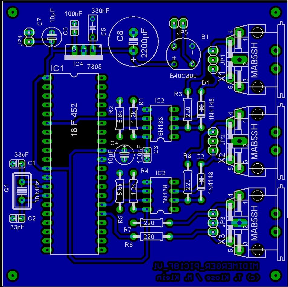
yes the connection from Core J2 to merger J4 is correct. you can see the right pins in the board pictures. but i've no idea why mios doesn't see the pic...
-
do you have access to a connectivity tester? a multimeter (you need the resistance test) works too. if you connect one tip or clip to the middle tip inside the hole on the front you can measure by probing them with the other cable which of the solder lugs is connected to the tip (R=0 ohms or a beep/light) one of the other lugs should connect to the outer metal sleeve. you can connect this one to the ground pin too so your metal chassis is grounded that way. on the core it actually doesn't matter which orientation you choose as there's a rectifier behind the pins.
-
interesting interesting!! that would be my next step, to design a 4x IIC out board and have Mike make it (and to be honest, have him check it and ask a bunch of not so clever questions too :blush: ) but... if there's gonna be some ...availability.... i might be able to not kickstart my brain :whistle:
-
there are a lot of VCF designs for the SSM2044 out there, one of which is seppoman's version for midibox, for use with sid or FM and the AOUT_NG: SSM2044VCF also interesting: SSM2164VCA
-
yep they are
-
funny, i've changed my mind again, so i don't need it. if you count on me i'll take it though. maybe i should anyway, just in case i change my mind again??:rolleyes:
-
i'd be in for one, definitely, in case you make them :)
-
earlier i used to drill those holes up to M3, but recently i grabbed some M2.5 screws and they work fine.
-
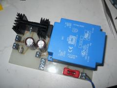 3 Ampère ? and you use Vregs in TO-220 package !! please please which Vreg are you using? i just know the 78Sxx / 79Sxx type that can deliver a max of 2A. but i need moar :rolleyes:
 -
man this machine looks totally awesome! i'm building my V4 right now so won't need it though. good luck!
-
yup mine too, and the new one too :thumbsup: thanks!
-
congrats!
-
AWESOME! many thanks! do you think it will work with the original AOUT also? i'm still not sure about how many gates are possible with the maxim version, but i think i remember 8... will have to study that soon...
-
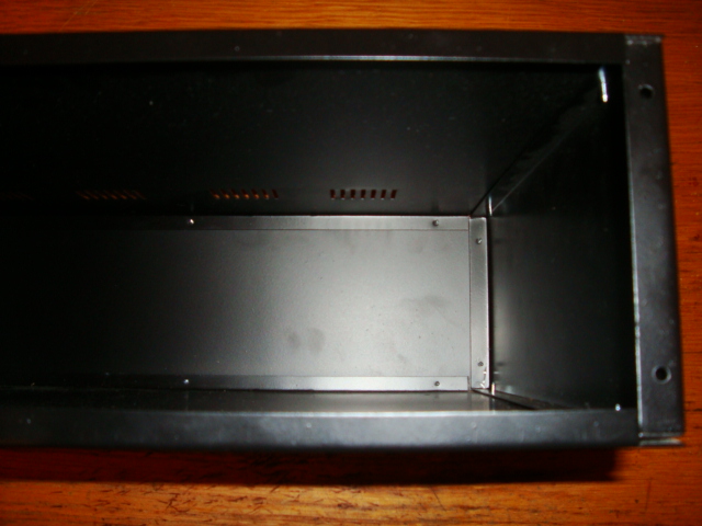
thanks jojjelito. the banzai stuff looks similar like the thing i have. attaching a pic of the ridiculous construction of the case. my plan was to bring the core to the backside and use its stock pcb mount midi sockets (core with hex standoffs on bottom panel). there are only a few more pcbs inside, 4x IIC, 1x AOUT (MAX525), i'll make a small perfboard with the additional sockets from the IICs in one row - and, the gate output buffers you mention sound very interesting. but the whole gate thing is some more stuff i'll need to dig out the info about even how to obtain them from the core or aout, we'll see. well, the case is deep enough to just cut it in halves and take the angled sides for mounting the back panels (one of which will be the so called front panel, which is nothing more than a wobbly blind panel). i'd have to cut away the angles anyways in order to fit in the control surface board. then i'll most likely get me a decent 3mm panel from Schäffer and knock some mounting holes through the sides to mount it to some kind of brackets that i'll have to make, also in order to make the side panels more stable, though the weight will be reduced a bit when cut in halves. in german that would be called "geknaupt"

-
hi guys! it seems i need some advice on the panel / case design. i'd like to build the Seqv4 into a 3HE 19" case. i bought a case from ebay, which turned out to be horribly shitty. i.e. the metal sheets don't really fit, apparently it's only supposed to look like a case. also the top, bottom and side panels are angled in a way that some sort of a 1cm wide frame reaches into the front opening (on which the front panel is supposed to be mounted). well the pcb definitely hasn't been designed for such a frame, it doesn't fit into it. so my guess would be there might be better cases for that project. what kind of case do you guys usually take? is there maybe some good quality recommendation? also i don't see any mounting holes on the fpd files to mount the panel to a case. there's just holes for the pcb/lcds and for mounting the unit into the rack, unless i miss something obvious here. so how is it planned, actually? how have other people done it? maybe i'm just imbecile? any hint would be highly appreciated :)
-
yup, your display says it's got the OPL3 test tone loaded, that would be for the FM synthesizer.
-
so now your really just inches away! you'll like it!
-
you'll need both the 15V and the ground from the supply.
-
yeah that's what i thought too, because it's very easy to do that part wrong and have all pins swapped.
-
also make sure you have the correct vreg for the 6581 installed (but even if not, i had 6581 running with 9V and that worked too) maybe check again that the two jacks on the ribbon cable are both oriented in the same direction (to avoid having pins swapped) besides that you could do some continuity checks (without power) between pins of ics that should be connected, maybe there's some weak solder joint somewhere
-
looks like a very decent job to me! it looks flat, is there room inside for more boards (or are you going to add a breakout box)? did you use on board transformer? quite obviously
-
ha, funny! i just found out i must have bookmarked the active content page! here it is: http://midibox.org/forums/index.php?app=core&module=search&do=active
-
yes that's what i meant. i've just removed the hosts entries, but that didn't change anything. it actually worked until the server move. but i've already gotten used to click through the forum sections again :)