

latigid on
-
Posts
2,524 -
Joined
-
Last visited
-
Days Won
149
Content Type
Profiles
Forums
Blogs
Gallery
Everything posted by latigid on
-
Here you go: http://ucapps.de/mbhp/mbhp_iic_midi_v1_0c.zip http://ucapps.de/mbhp_iic_midi.html is the parent page with all info.
-
I mean RS-422 is supposed to drive almost a mile, but I'm not sure if the MIDIbox would like that :).
-
Hi, We currently use this one from Reichelt: https://www.reichelt.de/d-sub-kabel-1-1-25-pol-stecker-stecker-1-8-m-2-0-m-ak-4010-p3997.html?&trstct=pos_0 TK. suggests up to five metres (so <15') would work but I haven't heard otherwise yet.
-
Might be my favourite one so far!
-
Hi Paul, The modules should be compatible with all Core versions. The digital gates etc. were typically done with GPIO pins for older Cores. Best, Andy
-
Impressive and elegant design crammed into a DIN socket with a 3.5mm jack output.
-
You cannot substitute for HC logic in this case. HCT is required to level-shift the logic to +5V, whereas a 3v3 3V signal pushes the threshold limits of a HC chip powered at +5V. 595-SN74HCT541N should be suitable.
-
True as far as I understand the structure of the chips, though I think the maximum current drawn could be 150mA per chip IIRC? Normally if they are overloaded the supply voltage begins to sag. In this case it's academic though, as we use bipolar driver transistors for both sides of the matrix. So the actual current could be somewhere near the ohmic value.
-
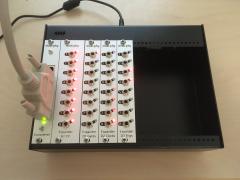
Four hours of stress testing just done. In MIOS Studio "set dout x 1" where 0<x<7 inclusive sets the sink sides active and "set dout y 0" where 8<y<15 inclusive sets the source sides active. I tested a mixture of red, green and mixed LED colours. No burn out or overheating of any parts. Colour and brightness after the test are identical to those of a non-stressed board (running in normal multiplexed mode for both). This doesn't mean that you should run your matrix like this (and if you did you would lose control over LED and switch registration), but it shows that a "failure" with the LED drawing the full theoretical current will not instantly damage the LED. At least there will be enough time for you to notice and reset the unit :-).
-
No worries! I know Peter and a few others ran a mixed colour scheme and it seemed to work out well, though the current drive through the LEDs might get a bit non-linear I think. Stress test is currently running with the "worst-case" matrix fully on, so no multiplexing. Half an hour in and nothings burned out yet. What do you think is a fair test time?
-
If you're concerned with the LED lifetime then simply increase the values of the RJ resistors to a current you are comfortable with. I would consider the probability of an LED matrix "freezing" in the way you describe as a low risk though.
-
Not sure if this is a grumbling post about schematics not being supplied? You bought the PCBs, so you are welcome to the schematics if you send an email in reply to your order confirmation. Snippets of the schematics are supplied in part throughout the troubleshooting thread. This is generally a better way to provide targeted help to builders and I'm very responsive in that regard. So, rant over! :-) If that wasn't your intention, then I'm sorry. The LEDs are indeed multiplexed as is typical for MIDIbox projects and driven through bipolar transistors. The key datum is actually the peak forward current per chip, listed as 100mA. True, our multiplexing speed and fraction is slower and larger than the given conditions. All of the LEDs have been put through a burn-in test using the same circuit as the one in the SEQ, so we know that they are good. Also, these are superflux LEDs with much higher current-carrying capacity than your typical LEDs. Have fun building!
-
Hi, We currently use this one from Reichelt: https://www.reichelt.de/d-sub-kabel-1-1-25-pol-stecker-stecker-1-8-m-2-0-m-ak-4010-p3997.html?&trstct=pos_0 TK. suggests up to five metres would work. So I guess that means 16 feet in Freedom Units. Unfortunately I couldn't find a decent one from Mouser but if you need to get all of your parts there, 571-1658613-2 plus 26-way ribbon could do the job (and would be less bulky than a cable). Another famous sequencer does it that way :).
-
It's getting there! Next in the pipeline is the LoopA, then the BLM.
-
-
The J16 port is physically the same on the wCore, the E part just breaks out the LEDs (GPIO) and reset switch to the panel. The Waveshare board of course might have layout differences compared to the Discovery. The pull-up resistors for the J15 display port required changes that I didn't fully investigate, but it works so I'm happy :).
-
I've reached the end of where I could offer help. If it was working before, switch back to a previous firmware version? I think TK. modified _NG to accommodate mixtures of AIN ports as inputs and outputs, so maybe something to do with that! Best of luck, Andy
-
Sorry, I see F4 in the title now. What version of _NG? If it's a recent version try an old one and vice versa. Could be a software bug. From a hardware perspective it might be that your analogue voltages are out of range? I.e., greater than 3V? If the MCU freezes it might have run out of memory and needs a hard reset. But reset from MIOS Studio typically doesn't work especially on Windows, or at least a restart of MIOS Studio is required. Personally I don't see the merit in using AINSER and AIN (MCU). The offboard ADCs are much better with far less jitter than the onboard ones.
-
F1 or F4 Core? AIN (MCU pins) or AINSER8 or AINSER64? I presume MCU. ?? What build version of _NG are you running?
-

The HAARP, a Hardware Advanced Arpeggiator.
latigid on replied to Antichambre's topic in MIDIbox User Projects
If you didn't already, add jumpers to the CAN pins in case the buss is used in the conventional manner (CV/gate). Putting a high-speed digital signal on the power cable might introduce some crosstalk and should be tested. -
Hello, Glad it worked out better this time :). I personally don't use the min/mid/max calibrations but rather the 0V--10V. If you switch the channel back to off and then try another does the issue remain? Could be a software bug perhaps, but if you can calibrate I think it's fine. Best, Andy
-
[SOLD] MidiBox Seq V4 with BLM 16x4 and CV/Gate
latigid on replied to secrethero303's topic in Fleamarket
Agreed, well done! -
 Now we just need to do black panels to match the case
 -
Nice! If you like it's also no issue to cancel the PCB order. But more DACs might be useful in the future. You can have up to 32 AOUT channels, so maybe a second A1 module set dedicated to CCs/LFOs? (I'm not 100% sure on the configuration.) So we can conclude from this that the DAC is at least somewhat resilient to reflow/extra heating?
- 135 replies
-
- 1
-

-
- line driver
- cv/gate
- (and 2 more)
-
I also remember a problem like this. But somehow I was able to get around it as I even made a video where I could vary the NRPN to access all 360 hues of a WS2812. I had a look at my NGC and could see nothing special configured. So please follow Bruno's advice, maybe he has found the problem.