-
Posts
2,524 -
Joined
-
Last visited
-
Days Won
149
Content Type
Profiles
Forums
Blogs
Gallery
Everything posted by latigid on
-

Relocation of keybed from main board not working
latigid on replied to Gregmidi's topic in MIDIfication
As you noticed, you can't extend ribbon cables this way as you end up "mirroring" the connection. Better would be to use a male IDC such as this: https://www.mouser.de/ProductDetail/Omron-Electronics/XG4E-2032?qs=sGAEpiMZZMs%252bGHln7q6pm%252bv5BXf4QdrTRziNjnmvfaI%3d -
I didn't want to spoil it!
-
Not enough UARTs for 8 MIDIO. You can expand with I2C (up to 8 output ports, perhaps inputs as well but normally only ins are used).
-
There will be Mouser BOMs available but they're still being finalised. Don't worry, Mouser ships very quickly!
-
Nice idea! How do you plan on attaching the assembly to the panel? Still screws through the acrylic? Or can you weld the spacer to the panel and use a tapping screw thread?
-
Hehe, yes you should! I've got a set of blue/green LEDs if you want some. For the 16x4, can you test the parts rather in stages? I.e. see if you can connect the SEQ to the Rx/Tx and check it works, then add the 16x4 then add the TPD. This should be doable by loading _NG and using set debug on in the MIOS Studio terminal.
-
As far as I can see, the split wiring is only necessary if you use separate DIN/DOUT modules. As you send/receive the full SRIO it should work with the J2_SI jumper installed and simple IDC10s.
-

LoopA V2 Introduction, Features & Support Thread
latigid on replied to Hawkeye's topic in MIDIbox User Projects
It's really a great little box! We'll order another set of prototype PCBs in the next day or two, then after the SEQ is all sorted we can think about getting the LoopA to a ready state. -
Also, thanks for the initial feedback on the v1.0 wCore boards. The breakaway option and microMatch headers were incorporated!
-
Really nice alternative method, thanks for the effort!
-
Generally quite good soldering but look for example at the resistor joints below the sandwich icon (fourth picture). Some could be cold, i.e. the fillet does not bond to the PTH properly. If the voltages check out, I'd also suggest to install the bankstick ICs and load the default presets. I don't know how the storage works without, plus there may be some inputs left floating.
-
Difficult to say without any photos (showing soldering quality etc.). Are you using stereo jacks for audio? JPB looks like an alternative power connector. Did you fit the jumpers left of MS1?
-
Possibly your MIDI interface is not passing the data properly. Do you have anything else to try, especially on the whitelist? The optocoupler is installed?
-
- 8 comments
-
LoopA has six ports (two ins, three outs and one "BLM" that could be used as a normal out or I/O combined on a DIN8) The v4+ has I2C (four outs) and MIDI8. MIDI8 is either 4I/4O or 3I/3O with a BLM. In case the BLM is used, the 7th DIN8 connector is redundant. But, you could use it as a power supply to the BLM and/or a +/-12V PSU. Wait until you see what Bruno's working on!
-
Nice offer, I would say that I'm interested in the covers to block all of these evil holes, but certainly we wouldn't be purchasing anything for a long time. If they can give an idea on pricing please let me know!
-
-
Pin 13 is /OE, so active-low output enable. It must have a connection to 0V/ground for the outputs to function. If there are other points already connected to 0V (i.e. it is not an interconnection or dry solder joint problem and somehow the plating is damaged ), then the right idea is to run a jumper wire.
-
We're still finalising the pricing. There are more PCBs involved than for a Wilba version, but also less shipping cost (and less hassle). I have a solder paste gun but I've never used it. But alternative build methods are appreciated! I try not to drag/wick as you can damage the solder mask and cause unintentional shorts. I find hot air is really useful if you've made a total balls-up though! As long as your iron is decent (small tip and temp. control) it's all about heating the SMT pad and wetting the joint properly while not applying too much solder nor overheating the chip. To do this, I hold the iron at a low angle (closer to the PCB) and just go half a chip row at a time. We will also make a "practice board" available that has examples of 1206/SOT-23/SOIC. Actually it is a MIDI thru splitter with DIN/3.5mm sockets, so if you do a good job you get a nice utility :).
-
one channel is defined to work as a 0-5V gate input!
-
https://github.com/lukas2511/STM32-USB-Keyboard There's a USBA host port, could be doable?
-
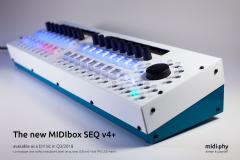
Yes, Peter requested a TPD-like addition. Still have to test and clear it with the case-master. SEQ V4+ will run also on a Wilba panel if the Core is STM32F4. The previous ideas thread had something like a v5 (e.g. RGB 16x4 matrix) but in the end it was mutually decided to make only subtle hardware changes to put less software support pressure on TK. There's a line driver DB-25 port, so all expansions are external. E.g. Altitude's AOUT, I will probably do one as well or remix my current design LEDs, same as on the Discovery but broken out on the front rear panel. One is acting as a Beat LED, three left for other functions (not assigned yet) Yep! And a stereo jack to boot, so one channel is defined to work as a 0-5V gate. We'll get going as soon as everything's ready :)
-
Allez les Bleus!
-
Please find the current thread here: Thanks for all of the discussion! Andy


