

latigid on
-
Posts
2,524 -
Joined
-
Last visited
-
Days Won
149
Content Type
Profiles
Forums
Blogs
Gallery
Everything posted by latigid on
-
Hello, The last things to make a BOM for are the sets of screws, washers, spacers. Although these can be bought from Mouser, I think the idea is to provide a set with the case. Especially standoffs (Abstandsbolzen) are super expensive from Mouser. We need to check what parts are supplied by Adrian and what we (or users) need to source themselves. At least there should be nothing more fancy required from Mouser. The M3 right-angle mounting brackets that are soldered into the MIDI8, I2C and USB PCBs are already associated with those PCBs. The DB-25 connector also has (I think imperial) screws for panel mounting. In the next case rev, the PCB mounting points will be used as well for extra stabilisation, hence we don't quite know the required number and type of standoffs required. Best, Andy
-
No worries, imagine the pain at getting these lists together!
-

dipCoreF4 and dipBoardF4, a compact Core.
latigid on replied to Antichambre's topic in Design Concepts
Chapeau!! -
Actually out of stock for another week or so
-
The only things I've added are basically ribbon cable and IDC headers. You don't need the USB-AB cable/SD card I'm sure. One of the pin headers was changed a week or so ago (now 929700-01-36-RK), if you bought the longer ones they'll still work but you'll probably have to trim them shorter. Also, there was a period where the multiple projects in a kit were not counted in the kit BOM, thus you might be missing Hirose headers (MDF7-10S-254DSA55). Should work out fine. Actually, the OLEDs don't use a backlight, so you can even leave them off.
-
Well :) We're waiting on a batch of cases and Peter's tutorial videos, but apart from that...! You'll notice that practically all parts are listed in the midiphy BOM modules, especially the Core and SEQ UI kits. It should be safe to order, but Mouser normally ships within a few days so you can hold off there too. Note that there are things there you may already have, such as an SD card and USB cable. It's just for completeness and for "easiest ordering possible." Maybe you still have a stash of IDC headers and ribbon cable etc., so you can remove what you don't need from the Mouser cart. If you like midiphy projects, stock up on SOIC 74HC595 and 74HC165, 1206 100n capacitors etc. as these are used quite often :).
-
Thanks, I fixed the resistor network! For the optocoupler, the 136 is 10x faster, maybe it needs other components altered? I will leave the 782-6N138 in for the moment, but there are a couple of substitutes available (859-6N138, 630-6N138-000E).
-
Please post here if you find a Mouser part is out of stock or has a long lead time. Please provide: Mouser part number or URL Board or kit where it is required (Optional) replacement part suggestion Note that end-of-life parts might remain in the tool until the supply dwindles.
-
Yeah, it's super difficult to keep track of what's current at Mouser. Often entire supplies of 20k parts just disappear or go end-of-life without much warning. I'll start a new thread and users can post when things are out of stock and Peter or I can update the backend. You only need 16 pins x 2 pieces (2x8 right angle header for the displays) so if you can find a cheaper one, go for it! We'll use Mouser as a reference for parts, but many of them could be substituted for cheaper ones. It's just a question of time on your side, extra shipping, things you may have in stock already etc. EDIT: sorry, I got confused about parts. You need a 2x12 normal pin header; this is to connect the Activity Matrix to lemec_R shift registers. Maybe a shrouded header will fit too, but we'd need to check with the next case rev.
-
dipCoreF4 and dipBoardF4, a compact Core.
latigid on replied to Antichambre's topic in Design Concepts
Fancy! -
Hello, Glad you liked the tutorial video! Peter deserves a lot of credit for these and he does a fantastic job. One of the pin headers is a bit too long. We are looking to replace 929834 with the 929700-01-36-RK part. If you've already ordered, no problems, but you may have to trim the pins a little shorter. It might also work with a standard single-row male pin header of about 6mm in length. Apart from that, I don't think there were too many changes in the last while. Agreed about your technique; I just put a blob of solder on there and cleaned it up after! (they are capacitors) The ribbon cable, IDCs, screws, nuts, washers etc. will be done as a separate "BOM" attached somewhere else, such as the case. Work in progress! Thanks again for the feedback and good job on the PCBs so far. Best, Andy
-
Peter's probably too busy to answer, but as he said above, he's filming the doku stuff now, which does take a lot of effort. We'd also need to place an order for cases. Other than that, everything is ready I think!
-
dipCoreF4 and dipBoardF4, a compact Core.
latigid on replied to Antichambre's topic in Design Concepts
Absolutely! I think Eurocircuits boards will be dependable right down to their minimum design rules. -
dipCoreF4 and dipBoardF4, a compact Core.
latigid on replied to Antichambre's topic in Design Concepts
Isolate is a polygon parameter that automatically keeps distance to routed traces, drill holes and pads. I am very conservative with isolate (0.5mm/~20mil). Clearance is the distance between two routed traces, also related is the distance between copper and a dimension (edge of board or slot). Conservatism is overkill, but the more conservative, the less chance of something going wrong. E.g. imagine a piece of dirt or dust on the photomask. If the clearance is too low, the fault might manifest into the production and short or cut a trace. Just because the fab gives low min clearance rules, doesn't mean they're a target. Just my opinion of course, please decide what's right for you. -
dipCoreF4 and dipBoardF4, a compact Core.
latigid on replied to Antichambre's topic in Design Concepts
Yep, BLM 16x16+X and 'ELO. No problems, just don't forget to set isolate to a reasonable value! -
dipCoreF4 and dipBoardF4, a compact Core.
latigid on replied to Antichambre's topic in Design Concepts
You use EAGLE, correct? One thing I remember is that slots are always a "hack" without proper DRC. You have to manually place keepouts/restricts on internal layers. Also note that some fabs will not like overlapping drill hits ("combo holes"); for them it's a risk that their drill or milling bit slips on an edge and breaks. -
dipCoreF4 and dipBoardF4, a compact Core.
latigid on replied to Antichambre's topic in Design Concepts
Sorry to hear Bruno. Where did you get your boards made? -
Song positions A1-P1 (16 parts) are also switchable on the selection row. You can also have A1-8, B1-8 etc. if you need more parts.
-
Hello, Check out the masterful SEQ beginners guide, particularly under "5.2.3. Save & Take over Patterns." This I think aligns with your idea. You may want to read about bookmarks, which are available as a related but different workflow controlling things like groups of mutes or the view type. Bookmarks are a selection-row mode on the midiphy. Best, Andy
-
Unified midiphy SEQ v4+ case backside
latigid on commented on Hawkeye's gallery image in Members Gallery
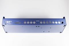 I think you'll even like this blue, Bruno :-) :P
 -
Simply use the compare function in the SVN and you'll see the changes are minor and will have no effect on anything that you do.
-
Commits approved by TK. himself. As the config uses conditionals based on the midiphy version, you've got nothing to fear when using other formats. Happy compiling!
-
Good point, but please be patient for the next 12 hours or so.
-
It's specific to the midiphy v4+, not to worry. The options should be broken out to the hwcfg file. But I would refrain from compiling this version for now.
-
Thanks for the great feedback! I don't use solder paste myself, but it may be easier to work with once it's a bit warmer, so I've heard of leaving it in your pocket or so. You can find out about SWD programming here: http://www.midibox.org/dokuwiki/doku.php?id=wcore The test-as-you-go idea is a good one; this would basically consist of checking SMT pins were not shorted together, that the +5V rail is good before applying power etc. There's not too much to debug especially on the I2C/MIDI8 boards etc. as they're quite simple. But a basic MIDI test would not be a bad idea. Best, Andy
