latigid on
-
Posts
2,524 -
Joined
-
Last visited
-
Days Won
149
Content Type
Profiles
Forums
Blogs
Gallery
Everything posted by latigid on
-
Just a few notes on SMT soldering. The process can be a whole lot quicker than THT, as you never need to clip a lead. It's true that you can't easily desolder chips, but the advice about hot air rework stations is sound. I've done the same before, even reusing 600 LEDs for the BLM. Practising on a test PCB is also smart. The die inside a SOIC chip is probably the same as in a DIP. The package and leads are much smaller for SMT though, and with DIY you're normally socketing the ICs. So overheating is an issue. I suggest the "tack" method to anchor one corner, correcting the alignment then going down just one row at a time. Hold the soldering iron at a low angle (close to the PCB) if possible and heat the pad, then apply solder to the pin. This keeps the heat source away from the IC and uses surface tension to wick the solder in. I suggest against "drag soldering" as it's possible to scratch the soldermask. For bridges, I've found an el cheapo solder sucker removes the excess quite well.
-
The SEQ V4+ (antilog) hardware is validated and we have some PCBs available, although the mechanism of the shop etc. is not quite ready. The last piece of the puzzle is the case, which is still in progress from Adrian. If you want something ready-to-go, with all through-hole compenents etc., then go for the Wilba version (contra: there's no ready-made case available and CNC-routed panels are quite expensive). SEQ V4+ features should be compatible with all STM32F4 versions; this includes both the Wilba and antilog variants. if you don't mind waiting a bit and want a "high-quality" solution/enhanced hardware suited to the current SEQ workflow, then the SEQ v4+ is the right way to go. it does involve SMT soldering, although it is not super difficult being 1206/SOIC. The Wilba version is certainly more straightforward in terms of the main control surface. the case from Adrian will make a "complete unit," hence we wait to see what Adrian brings :)
-
Hi, I thought it was around somewhere :) for LPC. Sorry about the outdated doku,,, Could you please try with the attached files? We need to get @TK.'s attention to get a proper build in the SVN. There may be a problem with MIDI; in this case try: SESSIONS/DEF_V4L/MBSEQ_C.V4 file: Old: MIDI_BUS_Options 0 0x00 New: MIDI_BUS_Options 0 0x01 midibox_seq_v4l_092_pre1.zip
-
Many have done the same. Some of the DACs seem quite sensitive to heat, which can result in a fully nonfunctional AOUT or weirdness on some channels. Could be the known issue of a 1:1 voltage divider: But it's already claimed to be okay for the quad VCA, if that's your usecase.
-

Issue with Sign-up and Contact forms, not working
latigid on replied to Nirokesan's topic in Miscellaneous
Notifications have also not been working for a while. @Hawkeye may be able to help. -
http://www.ucapps.de/ has the info you need. Best, Andy
-
Okay, so you want to record incoming note data and output that on a particular MIDI port. First, is your track set up to output on the correct MIDI channel? http://wiki.midibox.org/doku.php?id=mididocs:seq:beginners_guide:start#track_event To get something working initialise the track; you should get four steps of C3. Make sure that will play on the configured output. You can enter basic notes with the GP buttons and encoders. To record, use the following: http://wiki.midibox.org/doku.php?id=mididocs:seq:beginners_guide:start#entering_notes It takes a bit more effort, but should work. If things are not working properly, there may be an issue with your soldering or a MIDI feedback loop (the outputting controller is receiving the same data it's sending).
-
What are you trying to do? Set up for live recording? If you just want to forward the MIDI IN -> OUT, set up a router node as shown in the guide above.
-
http://wiki.midibox.org/doku.php?id=mididocs:seq:beginners_guide:start#appendix_3_the_midi_router
-
blm16x16 stop motion built video (music: crimic-fraktal)
latigid on replied to Phatline's topic in Songs & Sounds
Really cool, both the tune and the build! -
Nice job Peter! Looking forward to the software updates. Best, Andy
-
Hopefully all of your resistor networks are of the right type and soldered correctly?
-
Sorry for missing this; J9 is the power supply if you would like to supply it through the J1-8 headers. It's separate from the 3v3 supply. Here is the correct wiring (a bit messy) Yes. The SPI data/clock/#DC can be shared between a few OLEDs (e.g. ELO or SCS-OLED) with a separate CS to each display. Or you can power the displays directly from your PSU. Depends on the current etc. I think I did it this way as Core J10B is wired to 3v3 (3v0 on a Disco board). Generally the logic levels shouldn't be mixed. It's just a matter of how the display expects its data.
-
Just follow the normal LCD setup by defining the desired number of displays through the bootloader app. I think the first 8 are still selected by J15, but I'm sure you could configure 64 lines using the Disp Driver CS if wanted. It may be useful to power the driver at +5V if the OLEDs are locally regulated.
-
Similar, they are Matias Quiet Click. On the plus side, they are "more backlightable" than Cherry/clones, on the downside the keycaps are less readily available. But we have the supply sorted for anyone interested in PCBs. The quality and feeling is just as good if not better than Cherry.
-
Sorry for the lack of updates in the meantime. The last pieces of the puzzle are being worked on. Adrian has a tentative completion date of the end of April for case prototypes, so after testing these we will endeavour to keep our Spring target. :)
-
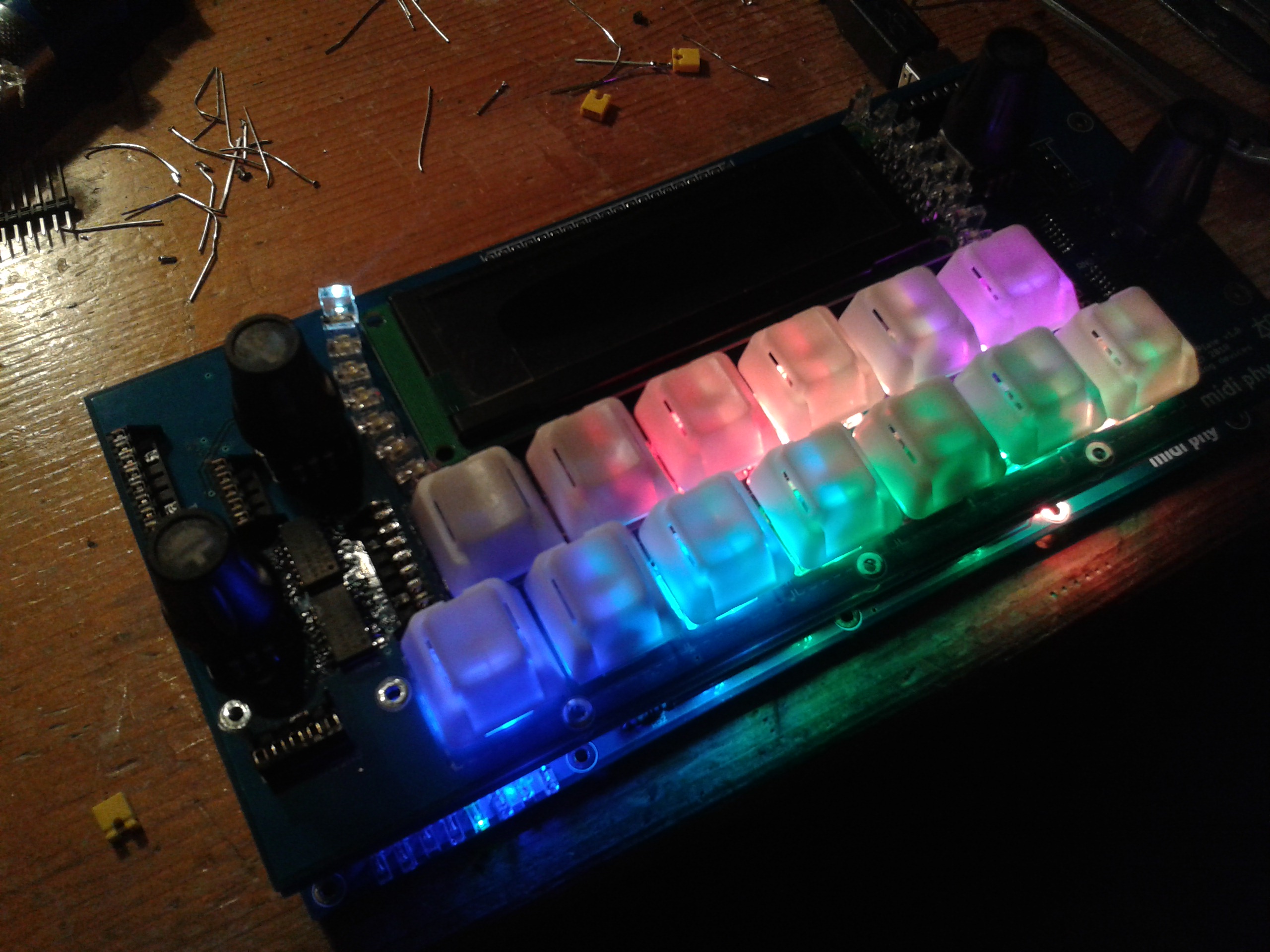
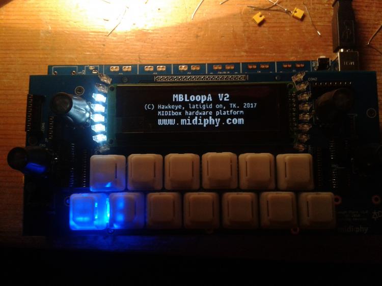
I've been working with @Hawkeye for about 6 months on an updated LoopA control surface. It uses similar hardware elements as in the SEQ v4+, most obviously illuminated Matias buttons. This time they will be full RGB :). A three-PCB set will be available at some point (no definitive timeframes available). The build is fairly straightforward but will involve SMT soldering (SOIC/1206) and creative pin bending. You can see the old CS in action here: Features at a glance: six tracks, quantise, note editing, more to be filled in :).

-
You can chain DIN/DOUT no problem.
-
Buy one, try it and report back.
-
@tedysuwarnady The board files are not open source, nor is there any plan to do so at present. Please send your shipping address if you're interested in buying a set.
-
This is the main thing. Well done! Your second photo represents the problem nicely: sub-optimal registration between the soldermask and copper plane. This, along with a) white soldermask that typically scratches easily and b) a 0V plane with tight clearance to the signal pads, can lead to these annoying ground shorts. I'm sorry for the hassle. This was a few years ago now, nowadays I increase the clearance :). One tip: you could get some enamelled copper wire for these little patch jobs. You could even salvage an old transformer and unwind the coil. To make a joint, cut the wire to size and melt through the plastic insulation to form a good joint. (see also Reichelt: FAEDELSTIFT WW)
-
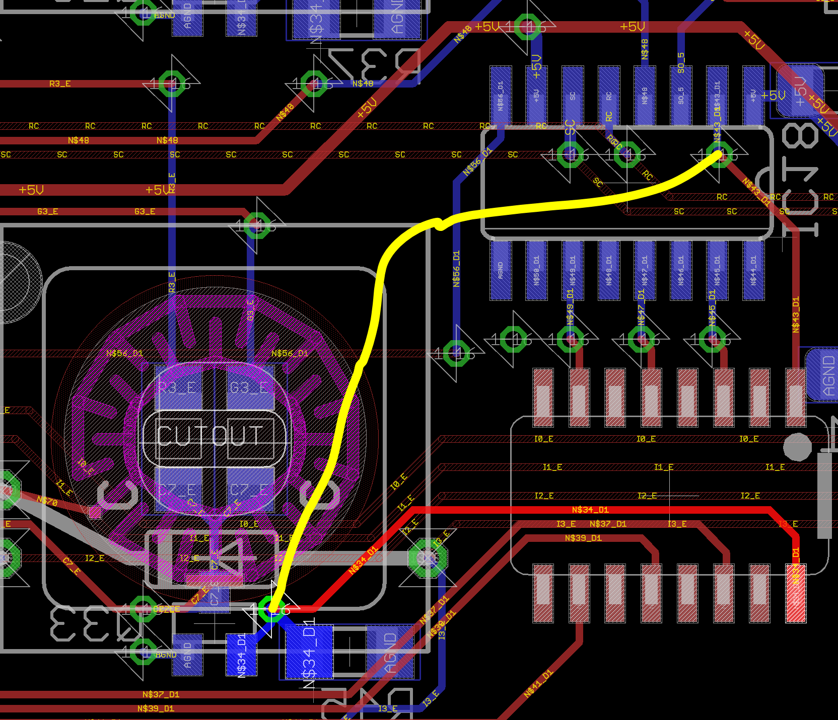
This current sink runs to pin 16 of RN18 You could try to bridge the current sink and pin 15 of IC18 with a 1k resistor as shown (actually to the SMD pads): The extra column LEDs are also connected to the extra row. If right LEDs fail to light, is this also true for every third LED (right-hand LED) on the extra row? (Normally I would count the extra column LEDs from the top; from your meaning I am guessing this is the third set of four using this counting system.) These LEDs are all connected to RN19, pin 10. Pin 7 of RN19 then connects to IC18 IC19, pin 5. Best, Andy

-
0204 is just the "wire link" resistor package. Notice one of the pads is connected to the encoder body, so bridging the TS parts as drawn as a "resistor missing a side" with wire will connect the metal surface to the DIN chain. Then something like a metal washer or custom CNC part can be connected to the encoder body using the thread/nut/washer. It was done like this so that the TS functions can be separate from the encoders if needed, and also that the metal surface can be "processed."
-
J10B is correct for STM32F4 Yes. I haven't done it myself, but the next 8 are there. No. Should work with n=16. 8 From J15, 8 from J10B For example: http://www.midibox.org/dokuwiki/doku.php?id=display_driver I have PCBs if you need. It's possible to get 16 CS lines from the Core, my version is a bit neater.
-
MBSEQ V4 works fine connected to PC but not on external power
latigid on replied to beautyofdecay_'s topic in MIDIbox SEQ
Please update the Discovery board. If you are using the old firmware, the ST-LINK side holds the main F4 MCU in reset unless a USB mini cable is connected.