latigid on
-
Posts
2,524 -
Joined
-
Last visited
-
Days Won
149
Content Type
Profiles
Forums
Blogs
Gallery
Everything posted by latigid on
-
A few corrections: Diodes are essential when the switches are scanned in a matrix, otherwise multiple switches would "activate" at the same time. Notice the cathodes of the regular LEDs and the diodes of the switches connect to the sinks on JD8. The anode sides of the switch diodes (drawn as the floating part of the switch connection) are scanned in on JD5 which will find their way to a 165 shift register. As the "strobe" pulses the transistor bases, the collectors allow conduction through JD8. The DIN pin senses this as pulling the input low and registers a button press. The MCU "knows" what button was pressed by considering what strobe pulse was active at the time. In effect, the current sinks are providing "ground" in a multiplexed fashion.
-
The display driver (~10cm square) is as shown: J15 connection top left (unfortunately I made a mistake and mirrored it...). To the right is a connection to the Core to generate a DOUT-like chain. The SPI data, clock and D/C signals run through 541 buffers and join with CS signals from 595 shift registers on the middle connectors. These have the pinout matching a (correctly oriented) J15 comprising only 4 CS lines. Works fine, as long as you remember to mirror J15! Let me know if you want a board. The board above has buffers plus damping resistors for all of the data lines. This means the Core MCU doesn't have to drive a long signal, which is better for performance. The RC termination as suggested by Peter can help. The capacitor effectively forms a lowpass filter that smooths out the spikes. It's not a question of drawing more current with a larger value, but lowering the corner frequency. At some point the clock transitions are too round to be detected and everything grinds to a halt.
-
You mention two different power rails, but is the 0V (ground) common to both or do you have separate PCBs? If the LEDs are controlled by the Core, then you might have weird current return paths as the 0V is shared there. Perhaps try to join the 0V rails of the PSUs together, or try using only one PSU.
-
As the "J15" port only supplies 8 CS signals, the others must come from elsewhere. Is there a discrepancy somewhere in the wiring/connectors?
-
The 595 only provides CS signals (relatively slow) so it's probably not that. Are all displays on the same PCB or is it split across multiple ones? The ribbon cable length seems reasonable. The Core PCB layout could be improved, but I understand the choices given the placement of J30. Something else I remember is that the Futuresonus Parva had trouble with OLEDs. I think the issue had something to do with loose component tolerances, meaning the displays went out of sync with each other at some point. You might try adding a manual reset switch. You can test this by briefly connecting the reset pin to ground. Perhaps it could be periodically called from a spare Core pin (would have to code it yourself) or using a timer/oneshot.
-
Hi Chris, The power-on reset circuit will only do that: hold the display in reset until the power stabilises. What you have looks like a frame shift error. My guess is that the clock signal isn't clean, and that after time data is shifted into the wrong "timespace" of the display. What is the wiring like between the Core and your displays? Also, please upload your images here or on the wiki so future travellers may see the issues you describe. Best, Andy
-
"antilog"
-
Depends how hard you drive the matrix, but should be okay Best to keep the colours the same per column.
-
PCBs have 2x 74HC595 each. So each is like an 8x8 matrix. I can't speak for TK. but you can look at the labelled diagram on the previous page and colour code things appropriately (play=green? stop=red?). Beware that current likes to flow along the path of least resistance, meaning you may get some bleed into lower Vf LEDs instead of the intended higher Vf one. Safest is to use only one colour.
-
Hi, The two le MEC PCBs are identical. Each column 1-8 gets its own DIN input. LED anode columns are arranged R1 G1 R2 G2 R3 G3 R4 G4 (red/green/blue are selectable) then repeated for the right half. The first two rows have two LEDs, only one for the third. Cathode sinks are four wide; first the encoder switches, then first/second/third LED/switch) rows. Then repeated on the right side of the PCB (encoder switch, first/second/third LED/switch row). Best of luck with your design.
-

OLRE16 with Lattice CPLD as Clocking/Addressing interface
latigid on commented on Antichambre's gallery image in Members Gallery
 Epic! Must be quite zen soldering all of those LEDs...!
 -
Did you fix the faulty connections? Could be: DISCO board not seated correctly Core header not soldered correctly Misaligned ribbon cable or improper connection MIDIO header not soldered correctly R3 not soldered correctly Short anywhere along the path to 0V (ground) Less likely is the pin on the DISCO board is fried or shorted somehow. You can try manually routing the signal with a wire or DuPont cable.
-
http://www.midibox.org/dokuwiki/doku.php?id=mb-lre8x2cs_pcb http://www.midibox.org/dokuwiki/doku.php?id=wilba_mb_6582_control_surface_construction_guide http://www.midibox.org/dokuwiki/doku.php?id=wilba_mb_seq http://www.midibox.org/dokuwiki/doku.php?id=sammichsid#sammichsid_build_guide http://www.midibox.org/dokuwiki/doku.php?id=sammichfm#sammichfm_build_guide http://wiki.midibox.org/doku.php?id=seq_v4l_mk._ii
-
Displays not initializing after working for a while
latigid on replied to EvilEvilEvil's topic in MIDIbox SEQ
Do your cables look like this: Notice both connectors face the same direction relative to the cable. On your one, one IDC is "up and the other "down" TK.'s has a bend on the left connector. I need a coffee, so not sure if this makes a difference electrically, but worth a try at this point. -
Displays not initializing after working for a while
latigid on replied to EvilEvilEvil's topic in MIDIbox SEQ
Better than a mulimeter would be an oscilloscope to verify the pulses coming from the Core pins, 595 and display. The voltages between ~0-5 are a result of time multiplexing I think, possible if the update rate on the multimeter is faster. If the display never initialised properly, the 595 outputs may be stuck waiting for data. -
Displays not initializing after working for a while
latigid on replied to EvilEvilEvil's topic in MIDIbox SEQ
MIOS Studio shows the SEQ application, you have to upload the Bootloader: http://www.ucapps.de/mios32/mios32_bootloader_v1_018.zip Where are you located? Perhaps you could send one of your LCDs to someone to test on known good hardware. -
Can I use a polar cap for the 330nF cap for C2 on the MB-6582
latigid on replied to fallenturtle's topic in MIDIbox SID
The polarised components should have the same orientation, i.e. follow the lower blue trace of C1. The positive leg of C2 is on the bottom, not the top as you have indicated. -
Can I use a polar cap for the 330nF cap for C2 on the MB-6582
latigid on replied to fallenturtle's topic in MIDIbox SID
No problem, as long as it fits. Be extra careful with the orientation if it's tantalum though... -
At the moment there is no AIN available nor planned for the SEQ. With a bit of programming it could work, but in the realms of what's already possible, the 16*16+X BLM can scan in four slider pots and there are still 4 AINs remaining. So there's a case for an updated BLM with a few CV inputs (+scaling/protecting circuitry). In my Quad I2C version, there are 4 AINs connected per PIC (16 total). It's a bit hard to find, but I think there is provision within the I2C protocol to enable AIN pins and send those as part of the data packet. The I2C stream would then need interpretation on the STM32 side. All of these tasks polling an AIN take a degree of run time. It's probably best to convert with another specific piece of hardware, be it MBCV or NG, or even a dedicated module. Once in CC message form it's easy for the SEQ to interpret. What particular parameters of the SEQ do you want to control with CV?
-
1st row normally shows triggered notes or the active step. Probably not. How do you know where the current step is? How do you know what triggers are active? Nope, but you can build your own firmware.
-
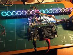
Nice Core :) Everything working okay?
-
MIDI out LEDs are sending clock messages at a high rate, so they appear on all the time. Have you switched to the MIDI monitor page on the SEQ? The CCs from MIOS Studio may not be mapped to anything, so you shouldn't expect anything to happen. It shouldn't matter if the driver says GM5 or not. You might be able to uninstall it and get a fresh update when connecting USB. Also, the USB drivers shouldn't affect the DIN MIDI outs. Try to set the port after connecting your synth then initialise the track. It should fill 4/16 steps with C3 I think. Maybe you were sending notes out of range?
-
First check the datasheets of both and make sure the mechanical and electrical pinouts are compatible. Then see if the main MCU is the same. If it isn't, it may just work, or it may require some firmware recompiling, e.g. if the clock frequency differs.
-
Heyhey! Cool track! What's going on, scene shifting or a bit of live recording? Still, a cool jamming/ideas/song creation box! I can't remember; can the whole clip be transposed? Best< Andy
-
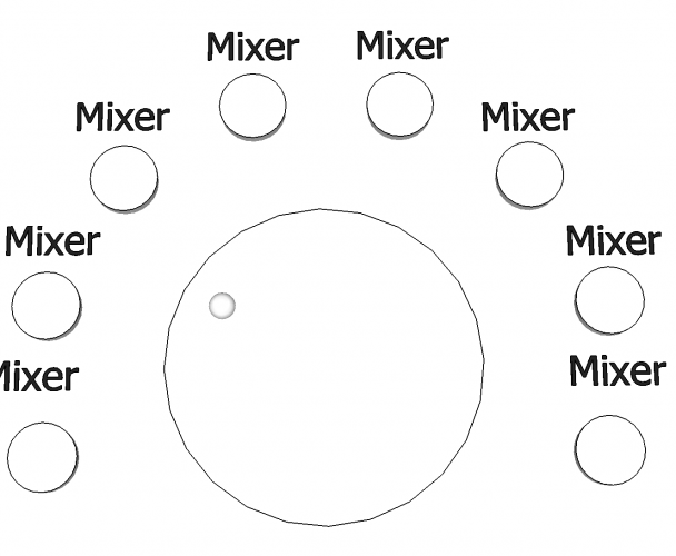
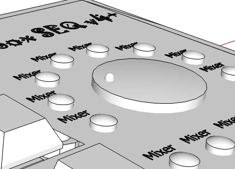
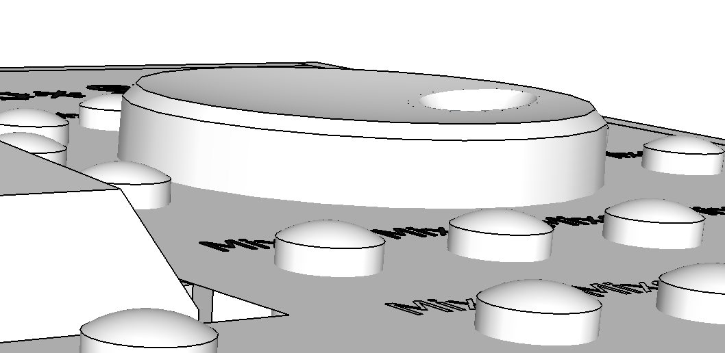
ALBS DK8,8-194 A.6/4,5 look pretty good. also Drehknopf DK30-105 "Small Dial" A.6/4,5 schwarz could make a nice datawheel and solves the complaints of size/height a few pages back: