

latigid on
-
Posts
2,524 -
Joined
-
Last visited
-
Days Won
149
Content Type
Profiles
Forums
Blogs
Gallery
Everything posted by latigid on
-

MB6582 powers on when Jack is connected
latigid on replied to dreamer's topic in Testing/Troubleshooting
Looking at the diagram here it's probably the expected behaviour, as +15V is always present. If the polarity was reversed the electrolytics would go pop and nothing would get through the regulators. So the next question will be about the 15VDC PSU, what is the model/do you have a picture? If it has a metal frame and earth pin, do you get continuity between it and the 0V line in the MB-6582? FWIW I did a similar mod on my build, but I use a linear (transformer-based) 12VDC PSU as input. This means that the device is electrically isolated via the transformer. -
MB6582 powers on when Jack is connected
latigid on replied to dreamer's topic in Testing/Troubleshooting
For me you still haven't explained the problem well. Because this is a modified build, you need to clearly document all changes here. Like drawing all bridges/cuts/substitutions/omissions on the layout file -- it doesn't have to be a work of art, you could use Windows Snipping Tool or a screenshot with a basic drawing program. Please don't expect others to go through all of the disparate threads and collate the info for you. I'm happy to try troubleshooting if you give some more info. And I repeat my "stupid" question above; does the MB-6582 power up only if the DC adaptor is plugged in and switched on? What is the voltage? What kind of PSU is it? How is the other equipment powered? It's important to check your wiring, because there are some complicated powering schemes possible in the MB-6582. Some involve adding two rails together which only works in certain circumstances, and also means "ground" is not always 0V! I assume you're only want to use 9VDC for the SIDs, which means you should come in with ~12VDC and regulate down to 9VDC. -
MB6582 powers on when Jack is connected
latigid on replied to dreamer's topic in Testing/Troubleshooting
What PSU are you using? The C64 one? Does the board pass the voltage tests like this? Do you mean it powers up with no PSU connected? That's pretty strange if so; perhaps you have a wiring problem in your house? You could have mains voltage where it shouldn't be. Check again through Wilba's layout that you've made the correct mods and upload an annotated image here to confirm. -
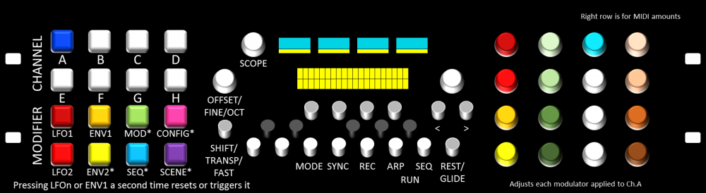
I'm still undecided on this, an ideal solution would be both! A Voice/channel mode that detailed settings are made for a single channel and a Performance/Multi mode where a set of parameters can be adjusted across multipul channels. An example of Performance mode would be the 4x4 encoders assigned to ENV2, you could control the ADSR of 4 channels without any paging. Right, so now we have three concepts of paging: 8/4/2 Voice mode (TK.'s choice) which is like a traditional MIDI-CV e.g. 4 voice with pitch CV, filter CV, gate and trigger; encoders are arranged in blocks within a voice and menus are used for finer tweaking. Single parameter mode (my choice) where all modulator depths across a single channel are accessible on one page, and specific parameters of modulators are on others. Each modulator is thus tweaked on a channel basis; see the mockup picture: e.g. Channel 1 is selected from the 4*4 button grid the encoders are colour-coded to match modulators represented on the bottom half of the button grid and adjust depth only on Channel 1. Env. 1 is pressed, the encoder field changes to yellow and all stages/other parameters can be tweaked. Unused encoders are unlit. For transpose and tuning, there's the "keyboard" layout of buttons and a dedicated encoder Multi parameter mode (your idea, kind of a hybrid between those above) assigns encoders to specific controls across multiple channels, e.g. ADSR of Channels 1-4. You'd have to make some judicial decisions when more than four useful parameters were needed. We'll have to test the hardware to get a good idea of the most useful workflows, but hopefully it's flexible enough to accommodate everyone's needs.
- 40 replies
-
- 1
-

-
- MBCV
- illuminated encoders
- (and 1 more)
-
Agreed about the dimensions, and following your suggestion these PCBs are 100mm tall, 420mm total width which will definitely fit in an 84 HP case. The only problem being that there's no room for the connectors -- as such a 126HP case (25.2"/640mm usable width) could be a better choice if you wanted them front mounted. The LRE board and displays etc. will be difficult to fit into 3U. The Wilba SEQ PCB is 121.92mm tall, which will is fine for 3U but doesn't take Eurorack mounting rails into account. My plan is to buy or make some sort of standard 19" road case and have the SEQ, CV and CV breakout panels mounted and powered off a decent triple PSU. Can you comment on your preferred layout of parameters? I.e. most functions accessible from encoders or more "voice" oriented pages?
-
Re-work of the V4L concept
latigid on commented on latigid on's gallery image in Schematics and PCBs
 It works with some creative pad arranging! But I agree, the D6 buttons are pretty good (I gave a few reasons in the V4L thread). In saying that they are quite tall (better for raised front panels though) and do have a bit of slop when pressed, so another option's not a bad thing.
 -
Re-work of the V4L concept
latigid on commented on latigid on's gallery image in Schematics and PCBs
Sadly no difference as the D6 pads are on square. I've got something workable just moving the other switch up 1.5 1.6mm, should be fine! -
6mm switches (4.5/6.5mm lead spacing) are now implemented with a 1.5 1.6mm vertical offset relative to the D6s. Any others? Prog. and Tempo labels reinstated.
-
Re-work of the V4L concept
latigid on commented on latigid on's gallery image in Schematics and PCBs
6mm ones with pin spacing of 6.5/4.5mm? Not sure if the fab will like the overlapping drill hits... Do you have an example layout or know of a board house that will do them? -
Re-work of the V4L concept
latigid on commented on latigid on's gallery image in Schematics and PCBs
I can try, what's your preference? Anything but TL1100, they go dodgy after a few years. See here also: -
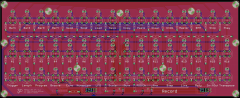
TK. asked me to rework the PCB, so after a bit of down time on a delayed train: It's the same basic layout as before, except that the shift registers are on board. This means only a single ribbon connector to the Core is needed = easy wiring. or could we feature-creep an LCD/OLED in? Accordingly there are some pullup/current limiting resistors added, but the 595 should be able to sink the cathode rows without transistors. 3* SOIC16 chips, 3 1206 caps, very easy to solder! The remainder is THT. OCD dummy resistor package if you want it to look more symmetrical Expansion header e.g. for DOUT gates etc. I adjusted a few labels, like changing Tempo to BPM to be more consistent with the SEQ, Program is spelled out fully it's progression isn't it? and Record modes are factorised. More mounting holes. Switches are the D6 type because: reasonably priced readily available multiple colours (and shapes like square and flat round) possible high quality, they still work well in a project I started 10 years ago It might be possible to add another switch footprint, so tell me if there's a particular switch you'd like to use and I'll see what I can do. I won't consider the TL1100 series because they exhibit serious problems with reliability after a year or two. As long as there's interest I'm happy to do a PCB run.
-
© 2016 latigid on
-
How about "Rude" as in Mackie's Rude Solo lamp? Maybe this mode could be implemented as a new parameter layer, which would give control over each step. If one step in a Rude# buss has a higher value its Gate will take priority.
-
Suggest to keep the detents, you have a good amount of off-axis torque on the large wheel. I think smooth encoders work well on more "analogue" controls, like the MB-6582. For incremental changes (low resolution, high precision needed for e.g. sequence lengths) stepped is much better.
-
I would hazard a guess that the caps are 20% or worse tolerance anyway? Have a go I say.
-
Hello, I used the recommended cutout size of 2mm, so your suggestion might fit (very snugly). The spec looks very similar, and the pricing is fair for low quantities. Drawbacks are that It's not specifically a reverse-mount LED and the lack of rear marking would make soldering them more tedious/error prone. They're also untested, but likely the same LED die. I still need to look at wholesale pricing, probably from China in full reels. For a bulk order I might be able to offer them at 10c each.
-
TM 4 BLM16 - TriggerMatrix remote via BLM16x16x
latigid on replied to Phatline's topic in MIDIbox User Projects
Looks like a really nice setup! Also good work on the BLM reimagination. -
Meine Programmierfaehigkeiten sind schlimmer als mein Deutsch! Aber ich glaube, dass du solltest eine Metaevent modifizieren. Dann man kann ins Editorprogramm die Taster und Event verbinden.
-
A real bible! Thanks so much for your considerable efforts!
-
SEQ-CS-Wilba + other Code, Scan Matrix
latigid on replied to Phatline's topic in MIOS programming (C)
As far as I know, there's no circuit diagram for the SEQ PCB, but you could trace the layout pretty easily. Are you familiar with the concept though? A button matrix scans inputs via DIN and sends pulses on the DOUT chain to close the circuit. It's not high-level programming, but you could load up MB_NG and define a button matrix to test the concept. @Sauraen just made a CS for his SEGA Genesis build, perhaps he has some advice. -
It's clear -- you need the threaded bushing in order to panel mount the datawheel encoder, in Wilba's case mounted to the PCB. I forgot you were using STEC encoders. It's no problem with voti or others. In this case Hawkeye's suggesting of filing down the shaft is probably the easiest. With the perfboard idea, I think it might be a bit unstable n'est-ce pas?
-
Question: did you "panel mount" the encoder to the rear of the PCB, bending the legs up to solder (or fly wired)? That's a good way to get the shaft length down. For mine it made the shaft a little too short (so the wheel scraped on the panel) but I spaced it with a bit of plastic in the D mounting hole.
-
Ah, maybe it's okay (didn't have the SEQ connected to anything)! I don't often use transpose myself, will have to look more closely. Best,
-
Cool update! But it seems that GP 13 or 14 can erroneously change the octave in some scales and keys (e.g. Root: C; 1: Harmonic minor, 11: Octatonic...?
-
https://en.wikipedia.org/wiki/Charlieplexing Wie TK hat gesagt, die DOUT Pins koennen ,,sink and source''. http://www.ucapps.de/mios_c_set_dout.html Baust du eine MIDIbox_NG?
