latigid on
-
Posts
2,524 -
Joined
-
Last visited
-
Days Won
149
Content Type
Profiles
Forums
Blogs
Gallery
Everything posted by latigid on
-
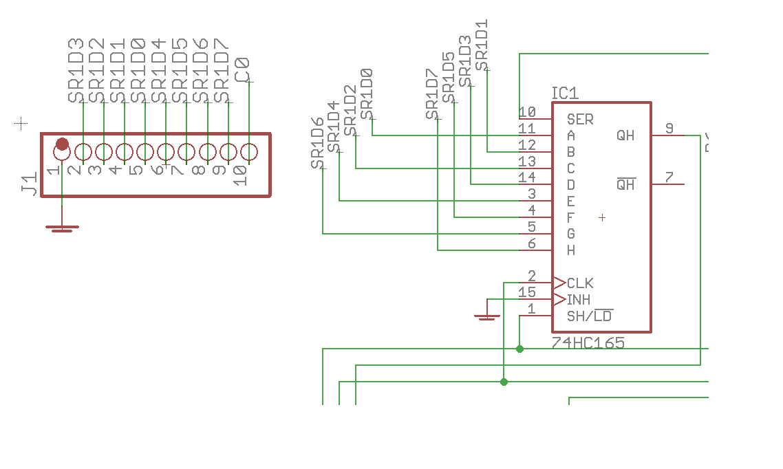
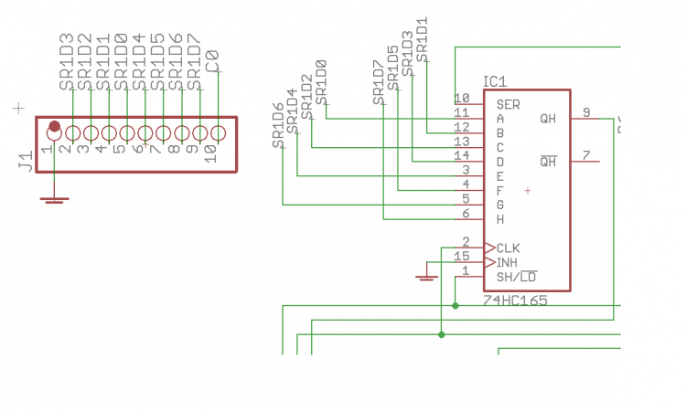
Trying the other encoder board means you swapped the other SEQ-plate onto le mec _R? Then the issue is probably on le mec_R. The encoder pins for ENSW3 are connected to pins 6 and 7 of J1 for both PCBs of the stack. Pin 1 is identified with a square solder pad (on the left when viewed from the top, so right-to-left if you're looking at the bottom of le mec). IC1 is the 165 shift register reading this encoder. You should measure continuity to pins 3 and 4 from the encoder pins. If not, check the soldering on the headers and that the interconnections are sound (were longer male pinheaders used?). You can also carefully short pins 3 and 4 to 0V (ground) and see if DIN events are registered. Use "set debug on". Here's a composite of what I wrote above:
-
Glad you're having fun! Something to do while locked indoors! :) You should find "Do Not Fit" notes on the BOM page (scroll down) https://www.midiphy.com/en/shop-details/137/47/midibox-seq-v4-lh-full-essential-kit- Just say if you need specific advice for a particular board. If you run out of shrouded headers you could also use a normal 0,1" dual pin header row.
-
Wow, looks awesome! Thanks! I know what you mean about side viewing though, sometimes you're peering into the next switch. Something like this is also used (I have no experience with it): https://www.keyboardco.com/product/filco-danish-and-norwegian-part-ninja-keyset-and-key-puller.asp (or just the one on mech https://mechanicalkeyboards.com/shop/index.php?l=product_detail&p=1411 ) With a different keycap set, go figure. But the wire puller grabs the diagonal edges. Good if you have to pull a whole QWERTZ/Y layout and have no single rows :)
-
Can we see? Would be the first SEQ with them! What tools did you use? A wire puller?
-
Sounds about right to me (could be a voltage meter/probe thing)! But if you've already ordered the replacement it wouldn't hurt to swap it.
-
All good, happens to us all! Without any input (i.e. DAC is not sending any voltage) all octal LEDs should be red, because 0/2048*gain - 5 = -5V. This also assumes all of the LEDs have the correct orientation. (As a sanity check, you can test the octal board with a binaire board to verify that all LEDs can be controlled.) It's possible that the op amps didn't appreciate the reverse power or the heat or both. So I would be tempted to replace all TL074s. Measure on both sides of R1, do you get a proper +5V reference? If not, consider replacing the LM4040. Viel Erfolg!
-
What rail is shorted? I always measure +12V-0V and -12V-0V or any rail to 0V before powering up. Photos of the board would be useful. Do all op amps have the correct orientation? What about the electrolytic caps? Check the pin headers J1 and J2 for shorts. 0V pins are in the middle, rails on the outside. The schematic just has all of the 1206 caps lined up, so it would be easiest to tell you where to look. It is a pretty simple circuit: the +12V is on op amp pins 4 and the adjacent caps (C6/8/10/12), -12V on op amp pins 11 and adjacent caps (C7/9/11/13). Check all around the power section C2-C5 and the beads L1/2 R1 is the voltage reference, so check there too. Good luck! Andy
-
J19 should work as connected! What rail is shorted? I can show where the rail is on a layout, that's probably easier. I would say to check the cable, but you're using a flying bussboard, so if another connector is fine then the issue must be on the transmute8. Best, Andy
-
Of course :) Best, Andy
-
 Amazing photos Peter! Thanks also to Adrian for the awesome case work.
- 4 comments
-
- 1
-

-
- loopa
- requantizing
- (and 1 more)
-
N'oubliez pas la Suisse romande!
-
Well done, #25! You can be a midiphy trusted builder now :)
-
Lack of beat LED was a bug introduced with a new software update a few years ago. Mute/unmute button behaviour has to be enabled and will also depend on the display mode. I can't remember the details sorry, but try different combinations of shift + extra column.
-
You could swap the resistors around or simply the pins in the HWCFG: # SR Pin ##default LED_BEAT M5B 0 LED_MEASURE M5B 1 # SR Pin ##swapped LED_BEAT M5B 1 LED_MEASURE M5B 0 There is also a setting in the options menu to invert the LED colours (MENU>UTILITY>OPT.; maybe this has an effect somehow?: OPTIONS page: new option "Swap LED colours" (relevant for Wilba and midiphy Frontpanels)
-
The observations suggest interference on this clock line such as antenna effects (EMI) from sub-optimal trace routing/cabling, or transmission line reflections. Hence a suggestion of an RC (resistor + capacitor) shunt termination (forum search will turn up more info). Grounding to the "chassis" seems an odd choice and means there is relatively high resistance between the chassis and system 0V. Otherwise the clock that is wired in parallel to all circuits would be shorted out, no?
-
Inrush current issue? Though the LEDs seem to be driven with 1k, so not terribly high. Grounding issue between power supplies? Check all 0V are common. SRIO integrity? Try buffering the J8/9 signal and/or terminating the chain with an RC shunt.
-
Hi Laurent, That's probably it, there is no power supply to the OLEDs in this case and they are likely parasitically powered somehow. Here you can borrow the jumpers from the v407 board: https://www.youtube.com/watch?v=QaN26uzUA1A&t=3357s I'm on holiday and the internet is too slow for me to find the tutorial step where the jumpers are inserted, but yes, you must connect the middle pin of J15_S to the 3v3 side. Hope that solves it! Best, Andy
-
Hi Adam, Nice work, thanks for investigating! Could you share the exact part that you used? Best, Andy
-
^Destpane is a variable, not a string. It's likely that there is a character limit on those.
-

XYZ-IR-Dome Controller (alesis photonX)
latigid on replied to Phatline's topic in MIDIbox User Projects
Maybe use an oscilloscope to trace the LED signal? What is it connected to? -
How about https://www.midiphy.com/en/shop-details/138/2/wcore-pcb-and-usb-pcb-midibox-diy-do-it-yourself-solder-midi-microcontroller-stm32f4 ?
-
I like the idea @k2z3k0 !
-
Nice, thanks for reporting back! Now trim that contrast!
-
Hi Laurent, The part is correctly oriented as pictured, with the "vertical" bar closest to pins 1/16. Bon courage! Andy
-
You'd need to reassign the pins, so use GPIO or a spare SPI for the SSD1206. Look maybe at the MBCV code?