ssp
-
Posts
660 -
Joined
-
Last visited
-
Days Won
4
Content Type
Profiles
Forums
Blogs
Gallery
Everything posted by ssp
-
Well I have been busy playing with the new Beta Emulator Modular software this week and when linked via my multitouch screen and using Ableton and Studio One it made a really nice touch controller system. The plan is now to strip the casing from the monitor and design a new casework for the monitor and midibox hardware. Looking forward to this one, heres a few pictures of my first day playing with the modular software. heres a few pics while messing with the touchscreen ;)
-
-
forgot to add, one of the biggest helps as well is i use acetate as well, if im checking the casework against component positions i print each one to acetate sheets and then everlay. examples in my bpm thread.
-
when i do my caseworks and front panels i work off the 2.54mm grid from the pad boards i prototype on. Then I try and use eagle, give the files to nils so he can have a good laugh and correct them where needed (everywhere) i then save a copy of hem as a dxf for the centre points of everything. I then load this into solidworks and check it against my case schematic and then adjust if needed. Works everytime for me, this is how i did the bpm casework and the humon casework.
-
ok after editing the asm file did you recompile it all? if not you need to recompile. are the pots linear 10k pots? if so ok, as for the grounding i never do that, i just set the number of cnx in the asm file then recompile, always works for me. have you set the correct number of mux's? there are many other issues, the simple thing to do is put a copy of your edited asm file up here and let us check it for you. Dont assume its right and that it is not the issue. Regardless of how you configured it , it may still be wrong. also a few pics of the assembly (soldering of the pins and pots etc, which pots you have used ie: make , model etc) by giving more information you help us to help you. need more input please....
-
thorsten my 3 gm5's arrived, many thanks!!!
-
arrived today many thanks thorsten
-
-
you saw it too?
-
No the edit events is built into the mb64e software itself, if you have the 16x2 lcd screen and you cycle through the built in menu system then you will see the edit event part and then you select that then press or move a controller, you can endit the cc# or what ever without connecting to a computer editor. The lcd shows that and what is assigned to it, you then edit it using the other buttons and then save it, to name the button you would need a bankstick attached. Also the mb64e allows both potentiometers, faders and encoders and buttons, and in my opinion gives you much more flexibility than the mb64, go for the mb64e you will not be disappointed. The editor from serge is great when you have meta events and such that you need to assign to buttons. I have used a mb64e and gm5 combined in my last two projects as they do everything i need them to do perfectly, the only thing i have not used in a project yet is assigning leds to douts per button, this is something im currently doing on my new project. The mb64e is is a great starting point yes you will need to do some code editing at some point and then recompiling but its easy (requires some reading and dont worry about asking questions!!) the tool links are available from the wiki pages. I was daunted by the whole thing when i first started, however as the whole thing is modular in nature and you remember that it makes everything seem much clearer. So you take a core and a dinx4, a 5 way ribbon cable with a molex header on the end and clip into one board and the other, there is your first core to din connection, then take an encoder and connect to pins 0/1 and vs and theres your first encoder, making sure that the code has an encoder set to those pins and not a button. If it needs changing then we change the code, this is something that I can go through with you when the time comes should you need it. The only thing i cannot do is build it for you im afraid!!! But thats the best thing about this place, lots of help if you put the effort in yourself, so, get a core kit from smashy's site, a couple of dinx4 and some ainx4 and a dout, encoders, potentiometers and faders can be bought cheaply here in the uk and i have links for those. I hope that helps a bit more.
-
the easiest thing for him to do is get a 452 core kit from smashy, see if anyone here has a gm5 chip and board for sale and buy that, hook the gm5 to the core via the digital inputs, this then gives him usb midi. If he then goes with the mb64e he can then use potentiometers or encoders or both with buttons, also he can edit each pot or encoders or buttons cc# using the built in "edit event" menu and change the control to whatever he wants without using a computer to do it, 2 second press to save and thats it.
-
As Hawkeye explained you will need the older core 8 with a 452, for what you want you will be better off with the mb64e this allows analogue and digital connections as well as led connections using the dout boards. What i always do is use a gm5 board and link that to the core using the digital pins, this allows direct usb connection to your computer rather than using the 5 pin midi ports on the core. Remember that the dinx4 uses encoders (endless) you will find some nice cheap ones here: http://cpc.farnell.com/jsp/search/productdetail.jsp?sku=RE04232 Also an encoder uses two pins, so if you connect it to the first pin which is "0" the it will use pins 0+1 the third leg will go to the Vs pin. As for the scrolling lights it will involve some code writing, however there is a wealth of information on the forum. The most important advice that anyone here can give you is to read, read and then read some more, everything you need to know is in these forums, spend some time doing a search, and then ask questions, try and quote threads so that other members have something to reference to with your questions. Most of all enjoy building something.
-
from my own experience building a few mb64e projects now, the menu system is essential. Using the built in editor for the mb64e allows you to edit every parameter for your controllers without having it plugged into the computer and then save it to the bankstick. It is also good to have for de-bugging purposes. The built in editor for the mb64e will allow you to edit the name for the control you are editing, the function as in cc#, note on, sysex, meta event etc, also the toggle state, on/off, radio button, or toggle, this is handy if you have a non latched button that needs to act as a latched button, you assign the toggle mode to it and hey presto its off state is 0 and its on state after a press is 127 (or what ever parameter value you assign to it). I love the mb64e so many possibilities!
-
oh dear.... dont let the door hit you on the way out...
-
im sorry but all im getting here is " i want to buy a pre assembled and pre tested core 32 kit because im too lazy to build it myself". Also the main crux of this site is to help people to learn about the midibox and also basic to advanced electronics and coding the software. The admins and the members go out of thier way to help people here, with references to the many threads that contain information on the related subject in question (as per find buddahs link in the above posts). There is also a live chat section where you can on most days talk to either Nils or Wilba also SmashTV along with other members about any relevent topic or just a chat in general. For years the members of this site have helped new members with as much info as they can, however, and I cannot make this even more clear, the main thing this community brings to you is the initiative to D.I.Y. Taking the time to learn the modules, to build them yourself and having the pride at the end when you fire it up and get some use out of it. This is what the forum trys to give you in return for purchasing one of its many kits. Midibox is not about making it economically or commercially viable, it is an introduction into the midibox software and hardware for those who want to learn to build,modify and use the projects listed here, for free i may also add. The only thing you have to do is put some effort into building the kits yourself, something you seem either unwilling or unable to do. Thats my two cents, now im going back to my current build project have a nice day.
-
if you do a search on the forum there is a thread that discusses assignment of leds relative to those in a virtual software synth. If i remember rightly i also asked some questions in that thread. here is one and here is the thread that i started.
-
all you need is a core running a 452 and an dinx4 one encoder and 10 buttons also a 16x2 lcd apart from that, some 10 way ribbon cable, some 10way idc connectors and some header pins. I always get them from rapid electronics as they are so cheap for components, you can get the core and din boards from either smashtv or mikes, search the forum for details on these. the encoder you can also get from rapid or even ebay, same with the lcd. as for a case you can use an okw case, they are small light and cheap, irecently used one for my mmc box using the midibox mb64e software you can make a nice little controller that will do exactly what you want. the first 8 buttons are for the menu system for the unit, handy to have these as you can quick edit them on the 16x2 lcd without connecting to a computer the next 2 buttons are your load buttons a and b the encoder is just for scrolling through your library. hope that helps
-
as the title says, happy birthday doug! sorry would have got you a drink but kitteh got to it first!
-
probably a diode across the power input stage i expect, i recently repaired a small desktop axiom controller and that had the same issue, also a red sound darkstar with advice from smashtv, that was just a diode also.
-
the easiest way i found was to edit the setup_midibox64.asm file. you will find this section: #define DEFAULT_NUMBER_AIN 64 <----this is the number of ain inputs if you only want 3 change to #define DEFAULT_NUMBER_AIN 3 #define DEFAULT_ENABLE_AIN_MUX 1 <----this is if you are using more than one ain such as an ainx4 if you are using one ain input not multiple change to #define DEFAULT_ENABLE_AIN_MUX 0 i found this much easier and quicker to do than grounding the other unused connections. all you need to do then is recompile it, check the mios wiki and thre you will find a quick start details on recompiling the asm file when edited along with the 3 other programs needed.
-

I give, Where do I hook up the navigation buttons?
ssp replied to jmayes's topic in Testing/Troubleshooting
the mb64 and mb64e nav buttons connect to the first 8 pin header on a dinx4 board or you can also make a single dinx1. you can also change two buttons for an encoder for data up and down values, this makes going through things a little faster also. hope that helps -
tldr
-
64... 32 excuse typo..
-
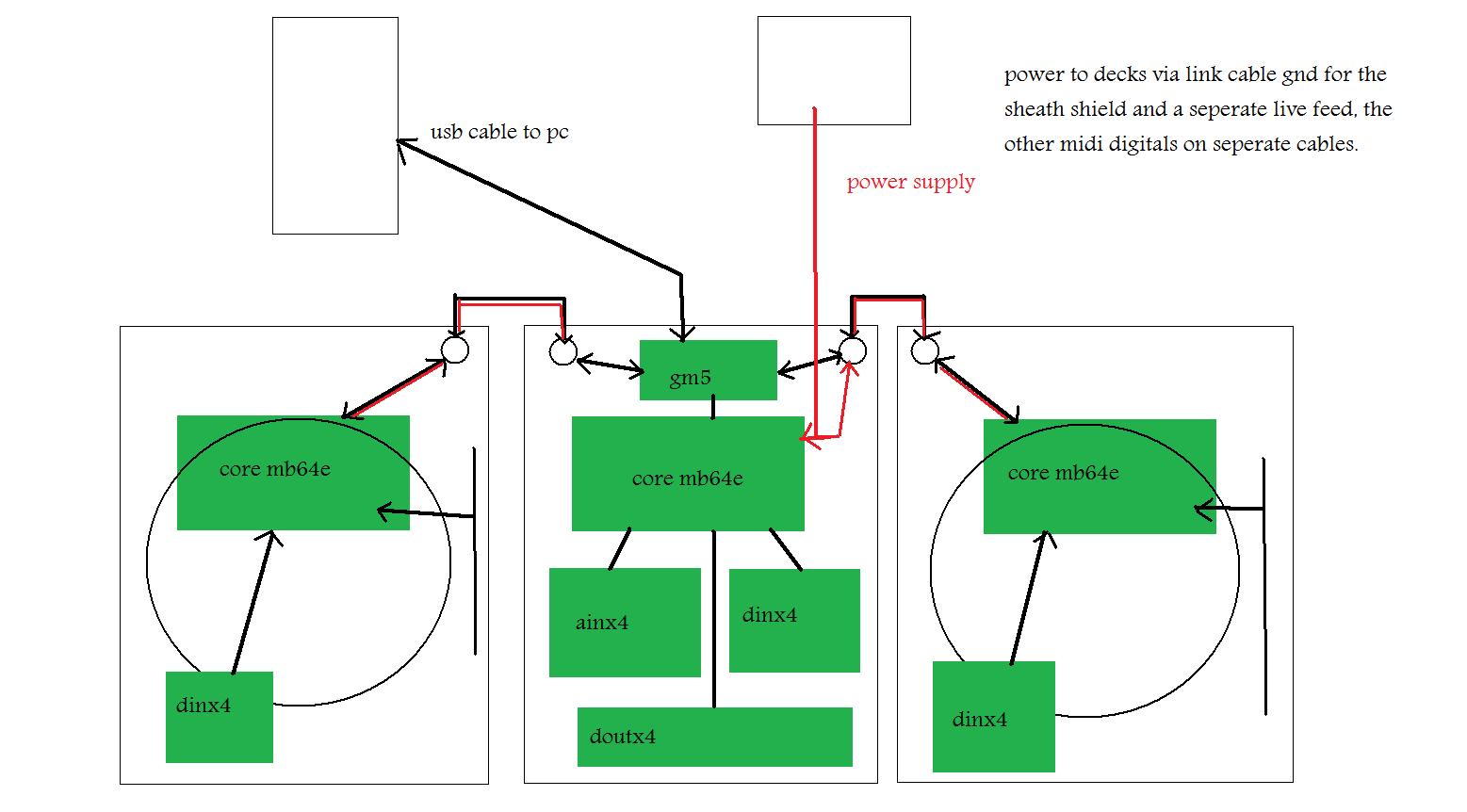
ok in the mixer put a core with a 452 running mb64e youre going to want this for the buttons. also ainx4, dinx4 and a dout for lights should you want them also a 16x2 lcd for built in editing of controls etc, also a 512 bankstick built onto a board as a permanent fixture. in each deck put a core with a 452 running mb64e 16x2 lcd, you dont need an ainx4 just use the headers off the core, you can ground pins you dont use however if you edit the asm file to just the pins you use, then you dont need to ground the unused ones. now to link the units. in the main mixer is a gm5 this is a single usb port with a single midi in and midi out physical port, however, the board still has 5 ins and 5 outs including the port 1 that is there. to link them you leave the 6n138 ic off the core once assembled, then you link from mi/mo (midi in/midi out) from j11 on the core, these goto the gm5 j6 pins. so as per this. mixer core to gm5 mi/mo 1 pins left deck core to gm5 mi/mo 2 pins right deck core to gm5 mi/mo 3 pins now the power, if you get a multiway cable then you can use a mini din socket, 5 pin mini din is fine and then you can have the digital mi/mo links and the shielded power feed also over a single cable to each deck. You can get power supplies that deliver upto 2.5 amps and 7-10volts which the cores need as a wall wart, or laptop style power supply which is what i am using. when you now connect your decks to the mixer, the mixer connects to your pc via a single usb cable, thats it everything data waise from the decks and mixer is sent back and fore via this single usb cable. you need to use the built in editor to give each unit its own midi id number as well, this will help when setting things up. when set up the mixer will have the single usb cable and the psu connection to it, then from the mixer to each deck. its a much more elegant way of doing things, i will do a diagram later today to explain it visually. basic picture to give you the idea.
-
The solution that i am using for my traktor set up is to put a gm5 in the mixer controller, then add two ports on the rear to link the two decks to via thier own cores, using the digital in pins on the gm5. By doing this everything goes through one usb output, so i link the mixer core to midi i/o pin 1 and the left deck to midi i/o 2 and the right to midi i/o 3. this makes things easier. the link cable is used with mini din sockets and connectors that are available from ebay very cheap along with the cable. Find all the components that you need, get measurements and do a 1:1 printout to check placement and interference when using. for the mixer all you need is a core, dinx4, ainx4 the dinx4 will be for the buttons and the ainx4 (you will need several) will be for the faders and pots (rotaries). The decks will need a core, dinx4 and a single Ainx4. Should you want indicator lights for the buttons then you will need some doutx4 boards as well. You can buy actual cdj platters as spare parts from the manufacturers, i just bought two large cdj600 platters from gemini spares in france for under 20 euros. They are around 8 inches or just over in diameter so a large platter/jog wheel which is better than some of the smaller type. I have to design a custom bearing mount for it that has an encoder attachment at the bottom of it to link to an encoder which will be assigned to the jog/scraatch commands via a shift button. Here is the platter/jog wheel. The pitch fader will be a 100mm slimline fader with centre bump and an led to show centre point also. I know it seems a little daunting but as flemming has said , read read read as much as you can, think of the core and the din, ain and douts as modules and you just link each together via a link cable, each button or encoder etc links to each pin on the relative board. Just think of it as a modular and things will fall into place. I am using the midibox 64e for mine as this allows the use of encoders as well as pots and faders, the 452 is what you will need for each core. The bankstick is handy if you want to name each control button, fader etc as this will show in the 16x2 lcd. Oh and some advice, get the lcds, they come in so handy for programming and debugging, with the mb64e you can edit all the parameters using the built in menu system. Remember the first 8 pins on the first dinx4 board are reserved for the menu system, keep them as is and it will save you many hours of frustration when editing without a computer to hand. Welcome to the forums!