

taximan
-
Posts
208 -
Joined
-
Last visited
Content Type
Profiles
Forums
Blogs
Gallery
Everything posted by taximan
-
Help needed....can i upload with only one midi cable...
taximan replied to florian's topic in MIDIbox SID
I am not the best person to give advice but for now please don't bang 19volts through it. cheers Paul -
Hiya, I was looking at getting the $39 option to 'mess' around with. http://meeblip.noisepages.com/files/2010/11/meeblip-micro-large.jpg cheers Paul
-
Hiya, I have the R1 (MBHP_SDCARD R1) from seppoman,is this the one you are after? cheers Paul
-
Hiya, I am about 75% done with my boards and will be quizzing you over the integration of the sequencer if you don't mind. cheers Paul
-
Snips!!! seriously? I would be crapping myself. I used a junior hacksaw (very fine blade) and was worried about using that...lol. cheers Paul
-
Hiya, There are a lot of more qualified people than me on this forum so my suggestions need to be researched properly. You already have the control surface and associated hardware (faders) so maybe the mbcv or something based around the midibox 64 would be the way to go? You can also get mbmf (automated fader controls. Just a couple of thoughts for you . cheers Paul
-
Here is a previous post from the seqv4l page Posted 10 November 2011 - 19:38Hiya, I found a strange little quirk with my lpc1769 board......here are the details. If I do not seperate the two halves of the lpc board before placing it on the core board,the lpc will not boot corectly,I spent a good few hours looking for dry joints etc in the header pins to no avail. However if I twisted the board ever so slightly the thing would boot up....it turned out my fingers were brushing against J5 of the debugging board making the thing boot up.....confused is an understatement...lol. Anyhow I put my other lpc17 (already seperated) on the same core board and it fired up 10/10....hmm only difference was the debugging board was not attached to this one.......so I attached it via the sockets suggested at ucapps.....aaaaa progress...this board would not boot up with the debugging board attached either........unless I touched J5 on the debugging board. Took the debugging board from the new lpc17 placed it in the core and bingo....it worked. So,looking at the ucapps tutorial on the lpc17 it seems that I have done everything that I should have but it seems the debugging board has to be removed for the lpc17 to work........or as is usually the case have I missed something? Anyhow....all is good now but I thought this might save someone else a bit of hair tugging. cheers Paul
-
Very dark......mucho likey cheers Paul
-
Hiya, Very kind of you,thanks. cheers Paul
-
No worries TK.....it's all part of the fun. I can take some pictures but am not sure what you would like in them,let me know and I will take some. cheers Paul
-
Hiya, I found a strange little quirk with my lpc1769 board......here are the details. If I do not seperate the two halves of the lpc board before placing it on the core board,the lpc will not boot corectly,I spent a good few hours looking for dry joints etc in the header pins to no avail. However if I twisted the board ever so slightly the thing would boot up....it turned out my fingers were brushing against J5 of the debugging board making the thing boot up.....confused is an understatement...lol. Anyhow I put my other lpc17 (already seperated) on the same core board and it fired up 10/10....hmm only difference was the debugging board was not attached to this one.......so I attached it via the sockets suggested at ucapps.....aaaaa progress...this board would not boot up with the debugging board attached either........unless I touched J5 on the debugging board. Took the debugging board from the new lpc17 placed it in the core and bingo....it worked. So,looking at the ucapps tutorial on the lpc17 it seems that I have done everything that I should have but it seems the debugging board has to be removed for the lpc17 to work........or as is usually the case have I missed something? Anyhow....all is good now but I thought this might save someone else a bit of hair tugging. cheers Paul
-
Thanks for another great project TK. cheers Paul
-
Thanks TK, At least I now know it's some kind of wiring fault (hopefully :blush: ). cheers Paul
-
Hiya, My cs for the v4lite looks okay................pity it doesn't work..lol. Just a few questions before I start dismantling it,I have used the following parts ..................... C9 is polybox instead of ceramic (on the lpc core) SN 74HC595N (on the lpc core) SN 74HCT541N (on the lpc core) I believe the SN prefix is the manufacturer and the N suffix is the package style. (on the above chips) Also I am still waiting for my sd card being delivered,will the v4l work without it? cheers Paul
-
PPPPPPSSSSSSSSSSTTTTTTTTTTTT Wanna buy a watch?
-
Nice tune............good driving music. cheers Paul
-
Hiya, Hawkeye thanks for the reply but I am just out of my depth with the programming side of things....(always been a bit thick).....I don't understand this bit......."maybe re-checkout via svn". Any chance of a nudge in the right direction? cheers Paul
-
Hiya, I have my v4 light built up now with the lpc1769 working and mios 32 opsys recognised in mios 32 studio,what I am struggling with is downloading the v4seq lite firmware from the repository. It seems I am downloading an empty folder? So.....can anyone point me to the correct file for download please? many thanks Paul
-
Me mucho likey :) cheers Paul
-
Hiya, Good idea,I have been doing the same but with two big balls of blutack. cheers Paul
-
I was doing a search for conductive ink to repair a display I have and came across this site http://inkjetflex.com More information here http://www2.dupont.c.../pcb/index.html And here http://news.illinois.edu/news/11/0628silver_pen_JenniferLewis.html Has anyone used this service yet and if so what is your experience/opinion? I won't paste anymore links as it seems that loads of info is available on google if you would like to look into this type of tech any further. cheers Paul
-
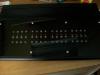
This is the version I knocked up,the buttons are 6mm acrylic rod with a slot milled in them to take the led's. I am just waiting for some parts from reichelt at the the moment and experimenting with labeling. cheers Paul
-
All the possible reasons for LCD showing only blocks/bars
taximan replied to Tim B's topic in Testing/Troubleshooting
Sorry.............. wrong advice I was going to give. -
Hiya Thorsten, Is there a schematic for the control surface available anywhere? I know you are looking at a complete pcb solution but I would just like to knock one of these up to play with while things get rolling. Apologies for being impatient but you know what it's like when a temptation is dropped in front of you like this. cheers Paul
-
Hiya, I sent one email to Doug at doug@midiboxaddict.com he replied the next day........just sayin. cheers Paul
