

John E. Finster
-
Posts
280 -
Joined
-
Last visited
-
Days Won
7
Content Type
Profiles
Forums
Blogs
Gallery
Everything posted by John E. Finster
-

Midibox SID - Wiring it all together
John E. Finster replied to ScarabOfficial's topic in MIDIbox SID
Hi, take a look at this. Here you can see a standard button/encoder wiring to a DIN module. On this page at the bottom you find other docs and infos about connecting stuff. But you don´t have to follow those wiring diagrams 1:1. You can simply connect the amount of buttons/encoders/leds (buttons/encodes to DIN, leds to DOUT modules) you´d like to use with your SID and reassign all the hardware components inside the firmware (look into the source code for a setup_*.asm file). Don´t worry, you don´t have to program anything, you just have to modify some variables, which are very well explained inside those setup_*.asm files. After you assigned all your hardware inside this file, you recomplile the code and get a "setup_*.hex" file to upload onto your SID. You can find the necessary infos about the needed toolchain and the procedures for compiling a Midibox firmware here. my regards -
Hallo, Wenn ich das richtig verstehe, meinst Du so was wie beispielsweise Rechtsdrehung = Note C und Linksdrehung = Note D, ist das richtig? Das wird ohne zusätzliche Programmierung nicht funktionieren, denke ich. Zwei Punkte sind da zu beachten bei Encodern: 1. Ein gerasteter Encoder gibt beim Erreichen eines Rastpunkts mehr als nur einen Impuls aus (encoderabhängig). D.h. wenn eine Tastfunktion damit gesteuert werden soll, kann es passieren, dass Du beim "Sprung" von einem zum nächsten Rastpunkt diese "Taste" mehrfach betätigst. Das muss nicht bei allen gerasteten Encodern so sein, aber bei den üblicherweise hier verwendeten ist das so. Es gibt die Möglichkeit, das beim Definieren der Hardwarekomponenten in der Firmware auszugleichen ("encoder type"), aber so hundertprozentig verlässlich ist das nicht. 2. Es ist richtig, dass ein Encoder an zwei DIN Eingänge angeschlossen wird (äquivalent zu 2 Tastern), aber bei Betätigung des Encoders in eine Richtung wird nicht nur ein DIN Anschluss angeprochen, sondern beide abwechselnd. Beispielsweise bei Drehung (mit DIN A und B) in eine Richtung wird nicht A-A-A-A-A-.... ausgegeben, sondern A-B-A-B-A-B-.... Dies hat zu tun mit der Möglichkeit, die Geschwindigkeit bei der Drehung zu erfassen und umzusetzen (glaube ich :rolleyes: ). Auch hier muss das nicht auf alle Encoder zutreffen, aber auf die üblichen schon. Es ist also nicht so einfach, zwei Taster durch einen Encoder zu ersetzen, leider... Hier kommst Du zu einer Wikiseite, die ein paar Infos zu verschiedenen Encodern hat. Was möchtest Du denn steuern? Vielleicht gibt es noch andere Möglichkeiten, deine Ideen umzusetzen. Liebe Grüße EDIT: Mir fiel gerade ein, dass deine Idee vielleicht software-seitig gelöst werden könnte mithilfe von if-Befehlen und relativen Encoder-Events. Habs noch nicht selbst versucht, aber denkbar wäre das schon. Ich kann nicht sagen, ob man das so hinbiegen kann, dass das auch mit den Rastpunkten des Encoders 100%ig übereinander passt, das müsste man halt mal ausprobieren.
-
Midibox SID - Wiring it all together
John E. Finster replied to ScarabOfficial's topic in MIDIbox SID
Hi and welcome, First, congrats on your progress with your SID. Regarding the display: I´m having difficulties finding a proper datasheet for this one. It might help if you told us where you bought it or, better yet, you contact your suplier yourself and ask for a datasheet. To be honest I´m a little confused. If you are not planing on using an audio jack at j3 (audio out!!!) how do you expect to hear the sound your SID makes. The midi connection itself doesn´t transfer audio signals, but MIDI data. If you want to integrate the SID into Reason the connections would be like this: SID REASON Midi Out ----------- Midi In (optional) Midi In ----------- Midi Out (required) Audio Out --------- Audio In (into your PC/MAC audio interface then into Reason OR into another Audio processing device entirely (Mixer, Amp, FX Gear,.....)) I´m sorry if I´m stating the obvious here. best regards -
Hi Spirit, I don´t understand muchabout what all the parameters do in detail, but I also had some success with different kinds of faders till now. So I can tell you what I learned so far: Here is an explanation another community member gave me regarding AIN and MF Deadband: With the individual parameters on the second page of the Mios tool you can adjust the "way" of the fader (sorry, no other word comes to mind). So, if your fader is driven to the ends with to much force (you hear a loud "clack" or the fader even jumps back) you can decrease the Min/Max Duty Up/Down values. If the fader doesn´t reach the end completely you can increase the values. I don´t know exactly what the relation is between MIN and MAX duty cycle though, for testing I put in the same value for min and max. You have to play with these values untill you find the right values for your faders. The MIN and MAX Value (20 and 1000 by default) is for limiting the highest and lowest position of the fader. If the fader "overshots" the end or doesn´t reach it, you could manipulate these values too. If you experience jitter while trying to reach the middle position, you can decrease the min/max duty cycle up/down values of the fader, that "calms" the fader while reaching the middle position. The voltage determines the speed of the fader, but also the noise a fader makes. Generally, faster means louder. If you are fine with 5v (speed and noise) you can leave that. That´s it so far. I will do some more testing next week with my new faders and maybe I have some new insights to share then. my regards
-
Hi TK, thanks for the info. I see now, what went wrong. It is definitely not necessary to implement a special option just for my seq4 built. especially, since even I consider this a minor issue. The main reason I brought this up here was, that I couldn´t understand if there were anything I could have done wrong. On the other hand, I can be sure now, that my seq4 works properly. Thanks again for the help and the patience. my regards
-
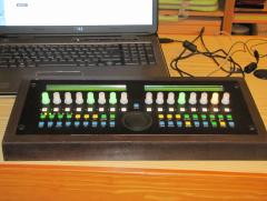
Hi, it´s me again... I was playing with my seq4 this morning and I was able to confirm my confusion again. when I´m not in the pattern screen, the green leds show the selected track, the yellow leds show the group. But when I change into the pattern screen, the green leds immediatly also show the selected group even before I press a track button to select another group. This seems inconsistent to me. If I had assigned some of the buttons to select a group, both leds would still show the group and not track and group. In the videos on the seq4 page (teaser 1&2), this doesn´t seem to happen. I´m wondering what I could have done different compared to the wilba-seq4. I´m sorry, if I´m completely on the wrong track and just babbling madly. My regards
-
Hi TK, thanks for the info on the motor voltage. I will try that next week. I was able to solve the jitter problem today. It seems to have been caused by the psu. After I changed the psu (more by accident than intent), the jitter stopped. As soon as I´ve tested the higher motor voltage, I´ll provide a feedback. Thanks again and my regards.
-
Hi, I´m testing PGFM3200 motorfader atm and am a bit troubled. 1. There are working generally, but they are moving slowly and not very smooth. After a night of testing different settings, I believe, the voltage of 7.5v might not be enough. Is there a way to raise the motor voltage to 9v or 10v? 2. Another thing I don´t understand. If I touch the lever, random midi events are generated around the fader position (e.g. fader value = 40 -> jitter value = 35-45). This happens independently from the touchsensor settings. I have to raise the AIN deadband to 25 minimum to make this stop. Is there a way to avoid this? Thanks and greetings
-
Hi, TK. Thanks for the answer. I don´t have my seq4 in front of me right now, so I can´t do further testing, but I might get back on this topic in a few days... Thanks again Greetings
-
Same here. Sometimes the core doesn´t seem to respond to MS no more for no apparent reason. Restarting the core and MS normally does the trick. You could connect the core via midi interface (if handy of course) and check if the core shows the same "symptoms". If so, there might be a problem with the core. If not it might be that your pc has problems with the gm5 midi driver that the Midibox uses (assuming you are using a windows based computer).
-
[ B ] Looking to buy a Midibox Seq (V4 or V4 lite) in the EU
John E. Finster replied to phillwilson's topic in Fleamarket
I wouldn´t buy it. First, it seems overpriced. Second, checking an already assembled box for errors can be a pain in the neck and very time consuming. I think it would be faster to build it yourself. And way more fun too.... The error could turn out to be a badly soldered part on one of the modules. In that case you could end up searching for days or even weeks before you find it. No fun, trust me... -
Hi, I´m a little confused by the track and group leds of my seq4: In my seq4 I only built in 4 track buttons with which I select the group, when I´m in the pattern screen. But I added 4 green leds for the current group as well as 4 yellow leds for the curren group. This works almost all the time, the current track and group is correctly indicated. But when I´m in the pattern screen, the green track led also indicates the current group. I was under the impression, that the track and group leds always indicate tracks and groups, even in the pattern screen. I tripplechecked the wiring and I don´t think this is a hardware problem. Is there something in the hardware config file I overlooked? Or am I missunderstanding somthing about the leds/button assignments or even the seq4 system completely? Thanks and greetings
-
The price is definitely unrealistic. And incomplete! The way I see it, for 50$ you get the board and the preprogrammed ATmega processor. But you have to get all the other parts too (listed in the bill of materials). So I estimate at least another 100$ for these. The led buttons on both sides (MECs) are pretty pricy. So can be the display and maybe other parts. At last you want to put that thing in some kind of housing, which can be also expensive, if you want a nice acrylic housing or an alloy frontpanel á la Schaeffer with an alternative case, you have to spend at least another 50$ for that. So, in a nutshell, with all the additional costs (shipping costs, unexpected extras,...) I would say, building the MIDIAlf would cost ~ 250$. greetings
-
My own SEQ4 - illuminated Enconders
John E. Finster commented on John E. Finster's gallery image in Members Gallery
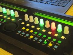 They are available here, but I also saw them with Mouser in US and a few others. I got mine on ebay, so I could not really tell about any experiences with this distributors. The translucent caps I got from Conrad. They are quite easy to implement. Besides the connectors for the encoder they have connectors for the switch and for the built in leds, wich share the same ground line. You just connect the leds like any other dual-colored led to a dout module and enjoy...
 -
- moved to another topic -
-
My own SEQ4 - illuminated Enconders
John E. Finster commented on John E. Finster's gallery image in Members Gallery
No, they´re not. They are illuminated encoders with translucent caps. I tried to build something like this on my own, but then I found these encoders and they were way cheaper. -
Hi, I´d like to present my first very own SEQ4. I will provide a more detailed documentation in the wiki soon. Currently I have another bun in the oven waiting to be finished :happy: . Many Thanks to TK and to the very helpful community. Greetings John
-
From the album: [John E. Finster] pics and such
-
From the album: [John E. Finster] pics and such
-
Du kannst alle EVENT_LED Zeilen einfach auskommentieren oder ganz löschen, wenn Du sie nicht brauchst. Diese Scripte sind alle erst mal nur Beispiele, wie man etwas machen könnte. Du kannst die Scripte beliebig um alle möglichen Ereignisse (Buttons, Potis, Endlosregler, Leds, Displays,...) erweitern, ja nach dem, was Du da bauen möchtest. Oder Du kannst direkt eigene Scripte entwerfen, wie gesagt, Beispiele gibt es genug. Ein Core Modul und ein DIO Modul reichen auf jeden Fall aus, um den Kasten zum laufen zu bringen. Damit Du Scripte benutzen kannst, brauchst Du aber noch eine SD-Karte, auf der die Scripte gespeichert werden können. Und Du solltest mal in die MB_NG Firmware Tutorials und Anleitung reinschauen. Die wirst Du auch brauchen, wenn Du deine Box mit Hilfe von Scripten programmieren willst. Zu empfehlen ist auf jeden Fall auch noch ein Display, da kannst Du eine große Bandbreite an möglichen Displays nutzen. Das kannst Du als Monitor nutzen, um den Midioutput sichtbar zu machen, z.b. fürs debuggen. Liebe Grüße
-
Hi, es ist möglich, anstatt 2 DIN Module auch ein DIO_Matrix Modul zu benutzen. Auf der Ucapps Seite zu den Dio_Matrix Modulen befindet sich ein Schaltplan dazu. Hier findest Du ein Script für Midibox_NG, im dem ein solche Button/Led Matrix programmiert wird. LG
-
Hi TK, thanks again for the very informative reply. I am getting closer by the day now :smile:. Greetings
-
Hi, I have another quick one. If I just want to connect 1 Fader (Masterfader) to the MF module, is it possible to leave out 3 of the L293D ICs? If so, do I have to bridge something? I guess, since those are analog inputs, I have to clamp A2-A8 of J2 to ground? Something else? Touchsensor connections maybe? Thanks and Greetings.
-
Yes, there is a bit of reading and learning involved at the beginning, but don´t worry. Once you have gone through the basics, a lot of information will just fall in place on its own. Check out, what others have built so far and a lot more becomes self-explanatory. SmashTV is always a good choice to get high quality PCBs for a very reasonable price. If you need other parts it can be wise to check local electronics dealers or ebay to avoid high customs fees (depending on your location, of course). Have fun! Greetings
-
Hi and welcome. What you definitly want, is to learn how to program scripts for the Midibox NG firmware. Basicly it works like this: You build a LPC17 Core Module (LPC Board + LPCXPRESSO). Once you have done this and have the MIOS OS installed (THAT you have to do before you start to build, but look into the ucapps site, everything is explained there), then you can upload the Midibox NG firmware and connect other modules (for connecting switches, pots, faders,.....) and write scripts to tell your Midibox, what it should do. It can be as simple as that :happy: . To start, I suggest, you look into the ucapps.de site. You find every module is very well documented there. You will also find a section for the Midibox NG firmware with some nice tutorials and a very comprehensive manual. If you get stuck or run into other kinds of trouble, you always can turn to this forum, it is a very nice and very helpful community, that will help you when you are in need of help. Greetings
