Search the Community
Showing results for tags 'stm32f4'.
Found 19 results
-
SSl Blog Post 02 Hello again, Last time I wrote about the design process of my console. In this post I want to focus on the electronic part. In the last couple of weeks I searched for the right knobs, faders and pots for the project and I nearly found all I need. The pots were the simplest part. I opted for the Alpha 10k Lin https://www.musikding.de/Alpha-Potentiometer-16mm-10k-lin Each channel will have one motorized fader. Here I choose the PSM01-082A-103B2. https://www.mouser.de/ProductDetail/bourns/psm01-082a-103b2/?qs=MAZTpT1IVl8rvdecO07rRA==&countrycode=DE¤cycode=EUR 14,76€ when I buy more than 25 is a good deal I think. The ones from alps are very pretty, but with prices over 30€ per piece they are quite expensive especially because I need 33. For the bus channels I opted for simple 60mm faders. Also 10k lin, not very investing. https://www.reichelt.de/schiebepotentiometer-stereo-10-kohm-linear-rs60n12-lin10k-p73870.html?&trstct=pol_1&nbc=1 The knobs where a little harder to find. For the Solo Cut and Rec knobs I want to have knobs with Leds which I can connect to an DOUT module separately. So I could press Solo on the console but deactivate it inside my DAW and the LED would follow my actions. After quite a bit of searching and some phone calls with distributors I finally found these. https://de.farnell.com/nidec-copal-electronics/cfpb-1cc-4w9/drucktaster-spst-0-005a-5vdc-panel/dp/3498758 The knobs inside the channel strip are still to be found. The need to be snapaction knobs with a white cap with the measurements of 5mm per side. I couldn’t finde the right ones even after quite some hours of searching. Maybe I’m just searching without the right search terms? Maybe someone of you knows the answer to that problem I didn’t start the search for LEDs just yet. I think and hope these should be easy to find. For the modules I chose STM32F4 for the cores, AINSER 64 for the pots and faders, NG MF for the motorfaders, DIN for the knobs and DOUT for the LEDs. I especially need quite a lot of AINSER modules and I’m still figuring out a way to connect more than two to an STM32F4. I found some blogposts but could get the answer out of these. They suggested it should be even possible to connect more than three? I obviously want to use as less cores as possible. This build will be huge either way. I can connect the MF modules directly to a pc without a pc. Thats what is written on the website. But how do I connect these to the pc? Via midi? There is no USB port on these modules right? And I also should cascade them. I need 5 modules. I want to use 33 motorized faders and that’s quite unfortunate because every mf module only supports 8. How do I cascade these modules? Also via MIDI? The last problem I ran into is the meter bridge. This could be a whole blogpost of its own… My plan was, or partly still is to use 10 7“ displays connected to a 10 times HDMI splitter, which tells the PC there is only one REALLY big screen. But after buying quite some displays to test out I figured out 90% of the screens for sale online are totally crap! Ok, I searched for quite cheep ones, but I need 10 of them and if I had unlimited money I would buy the original ORIGIN console… But I don’t have access to unlimited amounts of cash so I need a cheap display which works. The first one I ordered was the perfect size and easy to operate. But I only could see the image looking from one specific angle. Moving my head just a little bit the whole display would turn blue. The second one was advertised to be 7“, but the one that were delivered to my was only 3,5“…are you kidding me? Out of anger I searched for analog VU meters. I really like the looks of these and figured out these work with voltage. Is it possible to drive VU meters with a midibox module? Maybe with an AOUT module? So many more questions but I already wrote a whole book here…sorry for that. If you still reading in this point thank you very much! Have a nice day! Frederik
-

STM32F4 SDCARD Reading CID failed with status -256! Solved
gerald.wert posted a topic in MIDIbox SEQ
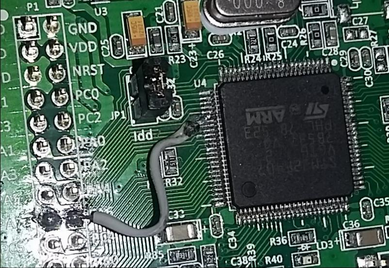
I had been getting the following error from the terminal when trying to access the sdcard on my STM32F4 core: [[35355.231] SD Card Informations [35355.231] ==================== [35355.231] ERROR: Reading CID failed with status -256! [35355.231] ERROR: Reading CSD failed with status -256! [35355.231] [35355.231] Reading Root Directory [35355.231] ====================== [35355.231] SD Card: not connected [35355.232] Failed to open root directory - error status: 12 [35355.232] [35355.232] Checking SD Card at application layer [35355.232] ===================================== [35355.232] Current session: /SESSIONS/DEF_V4L [35355.232] File /SESSIONS/DEF_V4L/MBSEQ_B1.V4: doesn't exist [35355.232] File /SESSIONS/DEF_V4L/MBSEQ_B2.V4: doesn't exist [35355.232] File /SESSIONS/DEF_V4L/MBSEQ_B3.V4: doesn't exist [35355.232] File /SESSIONS/DEF_V4L/MBSEQ_B4.V4: doesn't exist [35355.232] File /SESSIONS/DEF_V4L/MBSEQ_M.V4: doesn't exist [35355.232] File /SESSIONS/DEF_V4L/MBSEQ_S.V4: doesn't exist [35355.232] File /SESSIONS/DEF_V4L/MBSEQ_G.V4: doesn't exist [35355.233] File /SESSIONS/DEF_V4L/MBSEQ_BM.V4: doesn't exist [35355.233] File /SESSIONS/DEF_V4L/MBSEQ_C.V4: doesn't exist [35355.233] File /MBSEQ_C.V4: doesn't exist [35355.233] File /MBSEQ_BM.V4: doesn't exist [35355.233] File /MBSEQ_HW.V4L: doesn't exist or hasn't been re-loaded [35355.233] done. I checked around on the forum and had seen a lot of people having issues with wiring , the card slots and the format on the cards. Mine turned out to be bridged pins under the LQFP100 on the STM32F4 board. Here are the relevant pins if you are having issues as well: LQFP100 P1 PA5 30 15 PA6 31 18 PA7 32 17 PB2 37 24 Here is J16 looking down on it _________ | VS --- VS | -------> to ground | VD --- VD | -------> 3.3V (the STM32 actually only puts out about 3 volts) SI SO | SI ----> PA6 SO ---> PA7 | SC --- SC | --------> PA5 | RC2 RC1 | RC2 --> PD11 RC1-->PB2 (RC1 goes to the onboard SDCard reader or a card on J16 if there is no card in the reader ---------------- RC2 is for a second Card and not needed for most testing. I figured the board was already messed up so I decided to try fixing it. Those pins are super small and hard to work with. There was a dead short between PA6 and PA7 I was able to lift pin PA6 and cut the trace with a razor blade and solder a jumper directly from the pin to PA6. I would think this error would more likely happen from a solder bridge elsewhere and the STM should pass QC. The pins are pretty easy to test as they go straight to the ARM Processor. The also nicely went in order down the side. PA5 was pin 5 on that side of the chip. The white silkscreen on the board makes it a lot easier to keep track of the pins they are marked every 5 pins. The jumper might look a like it is crossing things in the photo but the pin is bent up and out so there is plenty of clearance. I tried solder wik, reflowing the pins, my hot air rework iron, cleaning between the shorted pins with a razor blade, and even removed the header pins hoping the short was there before lifting the pin but nothing else worked for me.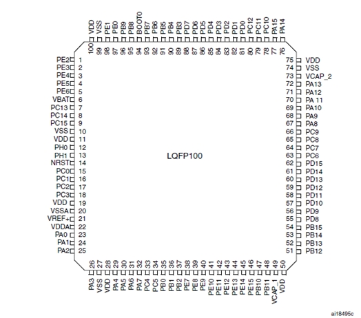

-
Hi everyone, using eeprom module in C++ code doesn't work, as there isn't extern "C" in eeprom.h, as far as I know. I've fixed this locally for myself by enclosing #include <eeprom.h> with 'extern "C" {}', but I suppose more general fix would be adding this to eeprom.h file. I'm sorry in advance if this isn't the right place for posting issues. Cheers, Djordje
-
Hello all! I've run into a problem while implementing a granular synth on a STM32F4 Discovery using MIOS32. The synth algorithm makes use of floating point operations - I thought it would not be a source of performance issue, since the MCU has a dedicated unit for floating point calculations. Actually, there are performance issues, because the FPU is not enabled for the compiler (I'm using the original toolchain). There's a line commented out in trunk/include/makefile/common.mk: ifeq ($(FAMILY),STM32F4xx) # leads to a crash - reason not analysed yet #CFLAGS += -mcpu=cortex-m4 -mfpu=fpv4-sp-d16 -mthumb -mfloat-abi=hard -mlittle-endian -ffunction-sections -fdata-sections -fomit-frame-pointer # works (but FPU not enabled) CFLAGS += -mcpu=cortex-m4 -mlittle-endian -ffunction-sections -fdata-sections -fomit-frame-pointer endif I tried to uncomment that line, it compiled, but crashed for real on the MCU. Do you know if there's a workaround for that? What can be the source of this problem? Rewriting the synth algorithm is not an option, this is my thesis project, and the deadline is close. Thanks in advance!
-
Another question about the MBHP NG platform: How to connect the Motorfader NG to new core32 without using MIDI (STM32F4)? Wich best way and protocol to use? (as well as MIDI I/OS on new core are already quite "pin-loaded") thanks in advance, Jerome
-
Hi, just wondering if the I2S DAC module still useful with the new core32 STM32F4?
-
Hi All, I hope this is considered the correct part of the forum for this. I am a novice midi to MIDI and a general tinkerer. Not much of a musician either.... I saw the Goom Synth build on the STM32F4 and thought it looked like good cheap fun. I have managed to procure the board, install MIOS32 and upload the synth "project.hex" without too much stress. I don't have a good way of playing the synth (no keyboard ATM) so long term I wanted to try using an old Motorola Xoom as a touch interface, similar to "ttfshtt" or "AVLG". Currently I have managed to connect to the tablet using the Cntrlr interface created by "Synthy" (for which I am very grateful) on both Win7 & Ubuntu Studio. All the above was done with two USB cables attached which is a bit of a pain, so I tried the PA9 to 5V trick. Although the board appears to power up, I don't get the pulsing LED LD4, and LD1 (Com) flashes instead of being solid red. By accident I have just discovered that if I plug in CN1 temporarily whilst CN5 and the jumper are in place, I can get the board to boot. Interestingly, it is more complex than just getting power on the CN1. If I plug the board into USB power block whilst connected to my laptop on CN5, it won't boot. I needs a laptop USB to trigger the board (hope that makes sense). Has anyone experienced this and have a cure? it is a pain at the moment, and I would like to try playing with MIDI commander on either my Samsung Galaxy, or Motorola Xoom as a control interface. (currently I have managed to at least see the Goom in MIDI commander with my Galaxy and a USB OTG cable). The board I bought from Farnell is the "STM32F407G-DISC1" which seems to be an updated (but I can't tell how) version of the STM32F407. Any thoughts appreciated.
-
Hi, I just finished building a CORE_STM32F4 with a MIDI_IO Module. It's connected with a MB909 MK-IV board but this is another story. I've noticed that 3V output, VDD output are @ 3V... I'd expect 3.3V ... By the way I'm looking into this because I've having trouble with the LCD: it's unstable. The best way to replicate: hold EDIT button, it makes at lot of message on the SPI, after few seconds the DOGM display becomes full white. The core is supplied with a 2A PSU. The sofwatre doesn't crash, can see SPI messages after LCD "crash". Anyway, the question is: 3V core pin, VDD core pin: are they normal @ 3V or they should be @ 3.3V (at least VDD @3.3V) ? This document is confusing me: http://ucapps.de/mbhp_lcd.html this PDF: mbhp_lcd_dogm128_mios32.pdf it talks about the 3.3V but it's unclear where I can get it on the STM32. Thanks
-
 Hi there, I have no virtualized Windows so I am trying to flash the bootloader with openocd: openocd -f stm32f4discovery.cfg -c "program project.bin exit" I get following output: Open On-Chip Debugger 0.9.0 (2015-11-28-15:54) Licensed under GNU GPL v2 For bug reports, read http://openocd.org/doc/doxygen/bugs.html Info : The selected transport took over low-level target control. The results might differ compared to plain JTAG/SWD adapter speed: 2000 kHz adapter_nsrst_delay: 100 none separate srst_only separate srst_nogate srst_open_drain connect_deassert_srst Info : Unable to match requested speed 2000 kHz, using 1800 kHz Info : Unable to match requested speed 2000 kHz, using 1800 kHz Info : clock speed 1800 kHz Info : STLINK v2 JTAG v14 API v2 SWIM v0 VID 0x0483 PID 0x3748 Info : using stlink api v2 Info : Target voltage: 2.891327 Info : stm32f4x.cpu: hardware has 6 breakpoints, 4 watchpoints target state: halted target halted due to debug-request, current mode: Thread xPSR: 0x01000000 pc: 0x0800637c msp: 0x20000c78 ** Programming Started ** auto erase enabled Info : device id = 0x10036413 Info : flash size = 1024kbytes Warn : no flash bank found for address 0 wrote 0 bytes from file project.bin in 0.001464s (0.000 KiB/s) ** Programming Finished ** shutdown command invoked I guess I need an offset, but how large? Thanks and best regards, Uli The following seems to work: openocd -f stm32f4discovery.cfg -c "program project.bin exit 0x08000000" At least it doesn't throw an error. But it shows up as "Van Ooijen Technische Informatica". Isn't this weird?
 -
Hello I want to finish my mbseq V4 with the new core STM32F4 i m not sure that i need 4 midi input so i wanted to know if i could used the quad IIC midi board with the STM32F4 for have 2 input midi and 6 midi output and the BLM output (2 input and 2 output midi come from midi I/O board for STM32F4) Zephyrin
-
I have an STM32F4 that refuses to work with both SD & ENC28J60 ethernet modules using MIDIbox NG & CV V2. Working: Ethernet and no SD When I boot it without an SD inserted, the ethernet works fine: Ethernet cable connected: yes Ethernet MAC address: 00:39:36:30:39:31 Ethernet services running: yes DHCP: enabled IP address: 192.168.0.100 Netmask: 255.255.255.0 Default Router (Gateway): 192.168.0.1 Not Working: SD and ethernet together (ethernet gets disabled) However, the moment I insert an SD card, I get various errors and the ethernet disconnects: [MIOS32_ENC28J60_PackageReceive] glitch detected - Ptr: ff09, Status: 7fb8 (max: 05ee) cd7f or [MIOS32_ENC28J60_PackageReceive] glitch detected - Ptr: ffff, Status: ffff (max: 05ee) ffff Working: SD and no ethernet If I boot with the SD card inserted, the MAC address is recognized but the plugged-in ethernet cable isn't detected (which could be due to another error): Ethernet cable connected: no Ethernet MAC address: 00:39:36:30:39:31 Ethernet services running: no DHCP: enabled IP address: not available yet Netmask: not available yet Default Router (Gateway): not available yet When this happens, my router actually recognizes the ENC28J60 and assigns it an IP address. Here's my cheap-o eBay ethernet adapter:
-
 Hi everyone, I have a strange problem with my STM32F4 Discovery not being able to communicate with MIOS studio. I flash the STM32F4 with the mios32 bootloader no issues via ST link, but then if I reboot the core and connect through the left Micro-USB, the USB MIDI driver doesn't come up on either windows or macOS (so I can't connect it to MIOS studio). If I boot the core in boot hold mode, the USB-MIDI driver comes up on both Mavericks or Win7 (MIOS bootloader) the core gets recognised and can upload an application (ID=0), but when I then upload midibox_seq_v4_086 and reboot, even though it works on the displays of my MbSeq4, no USB Midi drivers again in either Win7 or Mavericks. To test further, through boot hold mode I uploaded midio128_v3_019, reboot, and the drivers do come up and I can use the terminal, but I get 'No response from MIOS8 or MIOS32 core' (I've checked with all Device ID values, none works). If I now try to upload midibox_seq_v4_086 I get the 'Warning: no reponse from the core' message half way through and the core doesn't seem to send an upload request after booting. I have done this when the STM32f4 Discovery board is not connected with the MBHP_CORE_STM32F4 module and it exhibits the same behaviour. Is this midibox_seq_v4_086 messing up the USB midi drivers somehow? Or perhaps some residual code somewhere if it connects under boot hold? Any help is much appreciated!
 -
Hello guys, I am facing a stupid problem with a LCD (4x20) connected to the RTP-MIDI core... It simply does not start. I am sure that I forgot something somewhere, but I can't find what I have verified all lines under the bootloader using the testlcdpin command, everything is fine I have set the display size to 4 x 20 in the bootloader In my app, in the APP_Background, I have put this sequence : MIOS32_LCD_Init(0); MIOS32_LCD_Clear(); while (1) { MIOS32_LCD_CursorSet (0,0); MIOS32_LCD_PrintFormattedString ("TEST"); } but my display clearly does not even initialize (I see the "default" squares when I set the contrast to the max). Moreover, I was expecting activity on pins PA8, PD3 and PD6... but nothing at all (checked with my oscilloscope), like if the LCD driver did not start at all. What did I miss ?
-
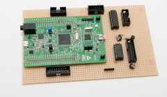
Hi all, I want to build the STM32F4 module pcb, but I'm not sure what the parts list is for what goes on the PCB. Is there a parts list anywhere for what goes on this PCB? Is there a SmashTV kit available that has all of the parts that go on the PCB, or would I need to order those from another supplier? Thanks, John
-
-
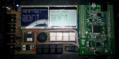
From the album: Tutorial
low cost STM32F4 MIDI Player Erster Erfolg mit dem Tutorial #019: A MIDI Player plays from SD Card© Elektrophantasten
-
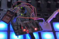
From the album: STM32F4-MoNo
final version of the prototype with more buttons and an encoder...© mOnO
-
Im planning a prototype of the stm32f4-core using the stm32f4discovery. unfortunately i cant find any notes on J28. nothing in the diagram and nothing in the mios32-include-files either.... basically i want to connect two ks0108 lcd-displays, which will need 4 cs-signals. on the lpc17-core they are provided via J28, but theres nothing like that on the stm32f4-core. am i missing something or is this just not implemented (yet) ?? mOnO
-
I noticed that a port to the STM32F4 Discovery has shown up in the MIOS sources. What is the status of the port? Is a new Core board planned? The STM32F4 parts have a few features that the LPC1769 doesn't, mainly a proper SD card controller that can use 1 or 4 bit modes instead of SPI, should be a lot faster; and an external memory controller for SRAM or additional Flash. Unfortunately the 100 pin part on the Discovery board doesn't expose all the pins needed to properly interface with external memories, but for synth/sampler-types of instruments the prospects of a MIOS with access to megabytes of fast storage is quite exciting I think :smile: The Discovery board does have the nice feature of an integrated audio quality stereo DAC, which I'd hope to see supported.