FantomXR
-
Posts
1,035 -
Joined
-
Last visited
-
Days Won
22
Content Type
Profiles
Forums
Blogs
Gallery
Everything posted by FantomXR
-
I took a look at the Core8 and I'd say that it should be possible to create a PCB with the STM with that size and the same pinout. Not sure if it makes any sense though. Anyway: If we want to use my pick & place machine it's good to have 5 PCBs or more of the same type at the same type. Are you guys familiar with routing and creating PCBs? Who wants to do it?
-
I'm happy to help you if you need some assistance. You are welcome to start a new thread I'll join in.
-
To be honest I can not follow you. I improved the design which I published here and used that in my other designs which I don't want to make open source. For example I changed the oscillator to SMD, I changed all none-VDD-traces to 0.2032mm, I changed all vias to round-style and 0.32mm diameter. I removed the ID-pin from USB. I added an inductor behind the USB connector for EMC-improvements. Also I changed all 0603 SMD parts to 0805. Those are a few changes I made in my other designs.
-
Since I just received the PnP machine last week I don't have enough experience yet to give you informations about prices. But yes: The PnP machine places all SMD parts which are not too high f.e. electrolytic capacitors. I didn't try double-side-partmounting yet. Regarding your comments: I use external optocoupler for MIDI I/O Micro-SD Slot is on the back of that PCB J6 & J7: I made some pcbs with faders which I connect directly to that connectors. There is no "current" version. It's a proof of concept, which worked. So I used the circuit around the STM provided in this design here in my other projects.
-
@Antichambre I could provide such service. The most time consuming thing is to set up the pick and place machine with the necessary parts. So prototyping (= only one PCB) will be a a lot of work. But for small series I would be open.
-
The sense behind this layout is just a proof of concept. My goal was to have an alternative to the discovery board. This design shows the minimal circuit which is necessary to get the STM running. This is why I left out almost all connectors from the original Core-Board. My goal was not to recreate a replacement because for my usecases the original board has tons of features I don’t need. With that said: you are invited to take the layout and adapt it to your needs. To be honest most of the connectors should be straight forward pin-to-pin routing from the STM.
-
Great!!! How did you mount ge STM? This was a tough part.... now with my pick and place machine it’s easy.
-
By the way: I meanwhile have a pick and place machine and improved the design which I populated here. So if there is interest I could produce some of those boards ....
-
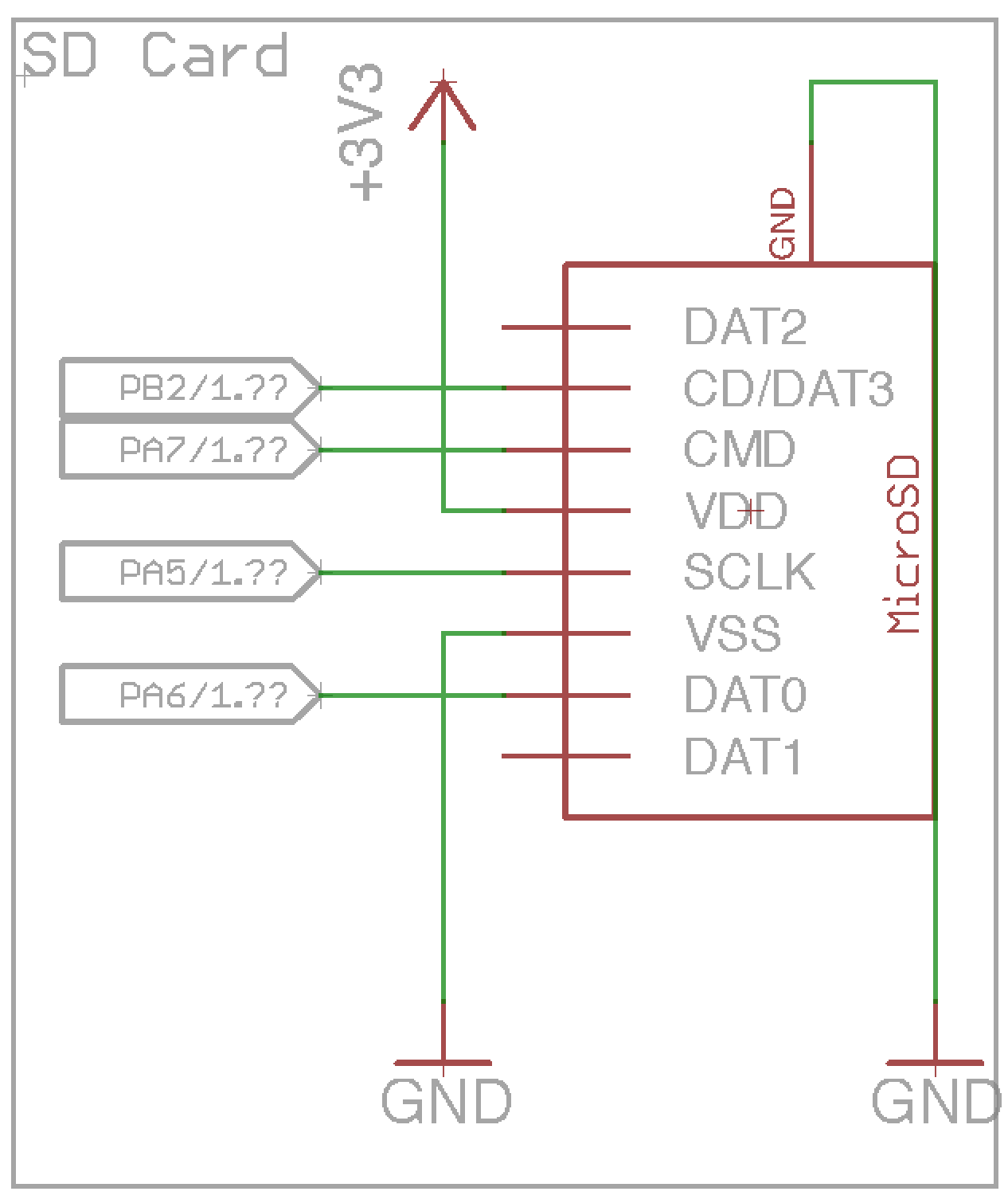
Great to hear that it works! I’m not at my computer at the moment. I’m not sure what kind of SD connector I used in that layout. I can look it up tomorrow. Either it is one that is called TF01 and I bought a bunch of them from Seeed-Studio but as far as I know they are not available anymore. That’s why I changed the connector to a Molex-Connector which is available at Mouser. I’ll look it up for you. Anyway: since the pinout is straight forward it is very easy to replace the connector in the design!
-
Hey people, does someone know a source for hammond-organ style rocker switches? Thanks, Chris
-
Hi frank, you won’t change the resolution by changing the keybed. You will get the same results. The problem is the NG firmware. So if you need a higher resolution, than go with KB. I use it and it works great. BTW: you can still use the break is make function by sending a SysEx command to the KB core.
-
SD-Card-Slot / Socket - Supplier Footprint and interconnection
FantomXR replied to Phatline's topic in Parts Questions
Actually it isnt, because it has a latch mechanism (not the push-lock like the others). You can open the MicroSD-slot and then you can solder it quite easy (IIRC). -
SD-Card-Slot / Socket - Supplier Footprint and interconnection
FantomXR replied to Phatline's topic in Parts Questions
Here it is ;-) MicroSD.lbr -
SD-Card-Slot / Socket - Supplier Footprint and interconnection
FantomXR replied to Phatline's topic in Parts Questions
I could provide an eagle-footprint for that one: https://www.mouser.de/ProductDetail/Molex/47219-2001?qs=sGAEpiMZZMuJakaoiLiBpmvbMAz4Ohc%252bCskVEZprFGs%3d Interested? Connection attached.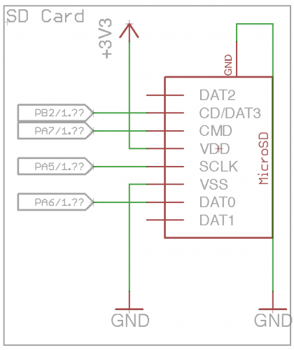
-
You can download it here: https://www.dropbox.com/s/9gkkxd1qafu9bfg/MinimalCore.zip?dl=0 I order my PCBs at elecrow. If you order there than you can do some improvements on the PCB like change all vias to a smaller diameter (0,32mm is minimum). Also the routing can be improved for sure. This was just quick and dirty to test the circuit. Meanwhile I used this design in other projects which are much more complicated than this. So I can confirm that the circuit works.
-
Na.... I'm very busy at the moment. So I can't do it for you. But I could upload the eagle-schematic / board-file so you can adapt it by yourself.
-
What "news" do you mean? This core is up and running. :-) Of course it can be extended to fit your needs...
-
Please .... I’m not amazon. I’ll get back to you tomorrow. I have no access to the PCBs today.
-
Here you can find a nice tutorial: http://wiki.midibox.org/doku.php?id=how_to_create_custom_glcd_fonts_icons_bars_for_midibox_ng
-
Where are you located? I have made a core, that has everything on board. Just connect the keybed and that’s it. I think I still have some units left. Let me know!
- 19 replies
-
- 1
-

-
- midibox kb
- fatar
- (and 2 more)
-
You set wrong IDs. Either you do fwd_id=sender:10 respective 11 and leave the rest as is. Or you change the IDs of the senders to correspond with the fwd_ids. Like this: EVENT_KB id=1 hw_id=1 type=NoteOn chn=1 key=any use_key_number=1 range=0:48 kb_velocity_map=map1 kb_transpose=0 ports=0000000000000000 fwd_id=sender:1 EVENT_KB id=2 hw_id=1 type=NoteOn chn=1 key=any use_key_number=1 range=49:127 kb_velocity_map=map1 kb_transpose=0 ports=0000000000000000 fwd_id=sender:2 EVENT_SENDER id=1 hw_id=1 type=NoteOn chn=3 key=any use_key_number=1 range=0:127 ports=1000110000000000 EVENT_SENDER id=2 hw_id=2 type=NoteOn chn=1 key=any use_key_number=1 range=0:127 ports=1000110000000000
-
Or you maybe could do it with a NGR script. I didn't test it, but this might work. Set up a button in your NGC like this: EVENT_BUTTON id=1 type=meta meta=runsection:1 range=0:127 EVENT_KB hw_id=1 id=1 type=NoteOn chn=1 key=any use_key_number=1 range=0:127 EVENT_KB hw_id=1 id=2 type=NoteOn chn=2 key=any use_key_number=1 range=0:127 In NGR you add this: if ^section == 1 if id(Button):1 127 set_active (id)KB:1 0 set_active (id)KB:2 1 endif if id(Button):1 0 set_active (id)KB:1 1 set_active (id)KB:2 0 endif endif And you have to add also this. Without this both KBs would be active on startup: if ^section == 0 set_active (id)KB:1 1 set_active (id)KB:2 0 endif
-
I tried it and I had no success. The first problem I ran into was, that the MIOS32_DELAY_Wait_uS only allows values up to 65535us.... not much. I will do some more tests.
-
I can do some tests today evening... I'll let you know!
-
I created some metas by myself already. So aren't you able to create a meta, that switches an LED (which is part of the meta-event) on and off with a delay of x-ms? I don't see why this shouldn't work... but I never tried it by myself... you could even add the delay to the meta-message. It's very easy to set up. You just have to edit the mios32_event.c and .h. You can use an already existing meta as example.