

Rowan
-
Posts
602 -
Joined
-
Last visited
-
Days Won
5
Content Type
Profiles
Forums
Blogs
Gallery
Everything posted by Rowan
-
The PCBs are pretty old. I got them from Smash about 10 years ago. When I connect the BLM to J2 on the DOUTX4 the upstream DOUT shift registers work but the DIN shift registers aren't passing anything downstream. If I take the DOUTX4 out of the equation and connect the BLM directly to the Line reciver it works (I haven't set up the HW config correctly yet). I've got the TPD at the end of the chain. I need to get out a DMM and see if the SI pins on J1 and J2 are connected. What I really should do is build the 16x16 BLM I got from you, that will solve the problem.
-
Quick question here. i want to chain a DIN's after a DOUTX4 module and looking at the DOUTX4 schematic I'm thinking I may be able to solder a jumper between the SI pin of J1 and the SI pin of J2 to pass the DIN data back to the Core.... Any ideas if this will work? I'll explain what I'm trying to do. I've got a MBSEQ (STM32F4 core) which connects to a AOUT NG and DOUTX4 via a MBHP Line Driver/Reciver, this works fine. I want to add a 16x4 BLM and TPD to this setup.
-

What is your BEST DIY synth? (open DIY project)
Rowan replied to DCO's topic in MIDIbox User Projects
@jaytee. Yes, I've seen the thread on Muffs and registered my interest. I already have a TTSH that I built about a year ago, it's by far the best SDIY project I've done to date and is now my most used instrument. I'm going to build another one if the run happens and I have the funds available at the time as its a VERY expensive project to source all the parts for. It cost me well of £1000 at the time and I expect it would now be closer to £1300 due to the weak £ Vs $. -
I've got a finished and tested AOUT_NG I could trade. im not really interested in selling it, I would rather trade for interesting SDIY PCBs/Parts.
-
What is your BEST DIY synth? (open DIY project)
Rowan replied to DCO's topic in MIDIbox User Projects
While the TTSH was available in my view was hands down the best DIY synth but was discontinued a few months ago. You may be able to find someone selling the PCB/Panel set but expect to pay a heavy price for it. It was expensive when it was available but now when I have seen it come up for sale it's REALLY expensive. Old Crow's crOw-BX looks good but I haven't built one so can't comment beyond that. The MIDIbox SID is really good and not too tricky to build, sounds good and different to most stuff that's commercially available. Mutable Instruments stuff is all very good, they no longer produce/sell DIY products but all of their products are open source so all the files are available to get PCBs made. Most of the really good DIY stuff now is in the Eurorack format. I ended up going down the eurorack route just because I built everything else I was interested in that wasn't eurorack. The best resource online for DIY synth projects is the Music Tech DIY sub forum on Muff Wigglers, check that out if you haven't already. -
The form factor of the DAC really shouldn't be a consideration in your design, the main concern should be accuracy. Choose a chip that offers the best accuracy then design around it. Number 8 wire theory at its best (@latigid on, I'm also a kiwi by birth;)
-
Leaded HASL please. I would also be interested in a PCB Euro panel to go with it.
-
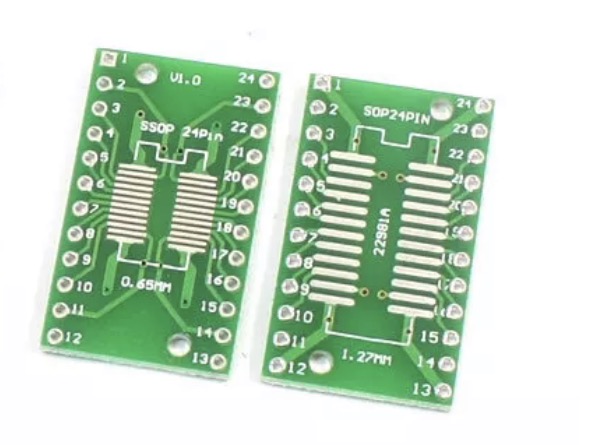
The adapter PCBs themselves are extremely cheap, the ones I pictured are about £2.95 for 20! To be honest, I would happily solder a few dozen ICs to these adapters if a bulk buy of the DACs was arranged. They could be sold with the AOUT PCB as a package. Let's face it, if you are going to by the AOUT board you're going to have to by the DAC anyway. The PCB could be redesigned so that a SMT DAC can be soldered directly to the PCB but also has holes to accommodate such an adapter.
-
Why not use something like this for the DAC? I'm sure someone on this forum could/would offer a SMT service be it free or paid. alternatively, you could have the PCBs produced with the DAC pre soldered. Some PCB manufactures offer this service.
-
I've come to like working with these type of SMT devices. With a bit of practice I've managed to get very good results, indistinguishable from machine placed components. My "technique" is to solder all the pins not worrying about solder bridges, the main thing being that all the pins are connected to the pads then use desoldering braid to clean up the joints. This is works every time for me even on TSSOP ICs.
-
I like the universal IO board concept you've come up with here, well done! Your choice of using the MAX525 is understandable as its already supported by the MBHP. I assume that you've come across mxmxmx's Ornaments+Crime module? He's using the TI DAC8565 which has 16 bit precision. I do understand the trade off here of 4 bits for THT but this is worth it in this case.
-
I also see some use for an abstraction layer for the hardware I/O. To me the logical place to do this would be the MIDI router menu. Hardware ports could be mapped to virtual port. Tracks are then mapped to these virtual ports. One nice side effect could be that only mapped virtual ports could be mapped to tracks thereby reducing the number of outputs avalible to a tracks to only ports that are used, assuming the physical>virtual mapping is set up correctly.
-
If you are using a Mac I would suggest buying 2x Emagic AMT8. These can be chained together for 16x16 I/O. They are pretty cheap second hand and will cost a lot less than a DIY solution.
-
Nice work!
-
Ive got a couple of suggestions for the V4 Plus firmware that I think would be nice. I appreciate that they would most likely take a lot of work to implement but I'll put the ideas out in the wild. Firstly it would be really good to have some on the MBCV features integrated into the sequencer such and the modulation sources like LFOs and EGs. While I know that the sequencer has LFOs I'm yet to find a way to send these to the AOUTs. If the above features are possible it would be good to have the max number of supported AOUT channels to 16 to be able to make use of these modulation sources in a modular system. Adding support for AINs and DINs would be nice. It would be great to be able to modulate parameters of the sequencer with a modular system. In many respects I think the MB SEQ interface would be perfectly acceptable to control a great deal of the MBCVs parameters. Of course you would lose the OLED scopes but I consider those to be nice to have but not essential. I could live without them. Anyway, just an idea that may not be possible.
-
The updated concept is looking good. It makes a lot of sense to stick with the standard MBHP line recover board rather than incorporate it into your design. Its actually almost identical to ( MBHP hardware wise) what I have in my rack. I've got a Line receive connected up on and AOUT NG and DOUT4X4 these have a total of 5 x CGS-96 Trunks modules connected to break all the connections out to 1/8" sockets.
-
I've got an assembled and tested driver/receiver pair I could part with. Maybe we could a trade on something, you always seem to have something I'm after.
-
I've been thinking about this problem and I wonder if it's down to the opto-isolatlor chip that was supplied with the LXR kits. @mongrolWhen did you buy your kit? I'll try switching the opto-isolator in mine and see if it makes a difference.
-
Which burning software are you using? I've got a PICKit3 and I use the Microchip software running on OSX. There is an option somewhere (I can't remember where) that you have to tell the software to power the chip while burning, it's somewhere in the advanced options IIRC.
-
Great news. It would be nice to know what it is that's causing the problem. From reports on the net the Elektron Octatrack has the same problem with the LXR. I have an Octatrack but I've never needed to clock my LXR to it but the Octatrack clocks perfectly to my MBSEQ.
-
I have an LXR and a MBSEQ and have experienced some strange issues relating to trying to sync the LXR MIDI clock sent from my MBSEQ. I take it that you are using one of the MIDI outs on the MIDI IO module and not a IIC MIDI out. If this is the case and you have IIC MIDI outs connected to you MBSEQ try driving the LXR with one of these. If you don't, try buffering the MIDI signal from the MIDI IO module with another MIDI device by connecting the MBSEQ MIDI out to another MIDI device that has a MIDI thru, then connect the MIDI thru to the LXR MIDI in. I'll put my money on this fixing the problem. There seems to be some about the MIDI IO module signal that the LXR doesn't like.
-
Cheapest place for Alps motorised faders? Any interest in a group buy?
Rowan replied to DubplateDerek's topic in Bulk Orders
Novski's webshop is here: https://vlrlab.com/19-diy You'll find all the info you need there. -
There may be a bug with the ethernet driver in the MBCV2 code somewhere. I have tried 2 different ENC28J60 based modules (the type that are sold to use with Arduino's) and both are displaying the same problem. Im getting exactly the same behaviour as @sneakthief did in this topic. I have used both 3.3V and 5V modules. The MBCV2 app is doing this (I'm using a freshly complied .hex built from the svn), but when I try the current version of the MBNG app (1.035) the ethernet module works fine. Below are some more details This is the response from the "Network" command in MIOS Studio when the MBNG 1.035 is running....... everything is working fine. [21998.725] Ethernet cable connected: yes [21998.725] Ethernet MAC address: 00:30:31:35:31:32 [21998.725] Ethernet services running: yes [21998.725] DHCP: enabled [21998.725] IP address: 192.168.0.10 [21998.725] Netmask: 255.255.255.0 [21998.725] Default Router (Gateway): 192.168.0.1 [21998.725] OSC1 Remote address: 192.168.1.101 [21998.725] OSC1 Remote port: 8001 [21998.725] OSC1 Local port: 8000 [21998.725] OSC1 Transfer Mode: 0 - MIDI Messages [21998.725] OSC2 Remote address: 192.168.1.101 [21998.726] OSC2 Remote port: 8001 [21998.726] OSC2 Local port: 8000 [21998.726] OSC2 Transfer Mode: 0 - MIDI Messages [21998.726] OSC3 Remote address: 192.168.1.101 [21998.726] OSC3 Remote port: 8001 [21998.726] OSC3 Local port: 8000 [21998.726] OSC3 Transfer Mode: 0 - MIDI Messages [21998.726] OSC4 Remote address: 192.168.1.101 [21998.726] OSC4 Remote port: 8001 [21998.726] OSC4 Local port: 8000 [21998.726] OSC4 Transfer Mode: 0 - MIDI Messages [21998.726] UDP Monitor: verbose level #0 This is the response from the "Network" command in MIOS Studio when the MBCV2 is running and SD card is connected....... The Ethernet module isn't recognised. [22234.657] Ethernet cable connected: no [22234.657] Ethernet MAC address: 00:30:31:35:31:32 [22234.657] Ethernet services running: no [22234.657] DHCP: enabled [22234.657] IP address: not available yet [22234.657] Netmask: not available yet [22234.657] Default Router (Gateway): not available yet [22234.658] OSC1 Remote address: 192.168.1.101 [22234.658] OSC1 Remote port: 8001 [22234.658] OSC1 Local port: 8000 [22234.658] OSC1 Transfer Mode: 0 - MIDI Messages [22234.658] OSC2 Remote address: 192.168.1.101 [22234.658] OSC2 Remote port: 8001 [22234.658] OSC2 Local port: 8000 [22234.658] OSC2 Transfer Mode: 0 - MIDI Messages [22234.658] OSC3 Remote address: 192.168.1.101 [22234.658] OSC3 Remote port: 8001 [22234.658] OSC3 Local port: 8000 [22234.659] OSC3 Transfer Mode: 0 - MIDI Messages [22234.659] OSC4 Remote address: 192.168.1.101 [22234.659] OSC4 Remote port: 8001 [22234.659] OSC4 Local port: 8000 [22234.659] OSC4 Transfer Mode: 0 - MIDI Messages [22234.659] UDP Monitor: verbose level #0 When the MBCV app is loading the SD card seems disable the ethernet module. [22185.516] [UIP_TASK] DHCP Client requests the IP settings... [22185.518] [CV_BANK_PatchRead] read patch A001 [22185.518] [CV_BANK_PatchRead] read patch A002 [22186.520] [MIOS32_ENC28J60_PackageReceive] glitch detected - Ptr: ffff, Status: ffff (max: 05ee) ffff [22186.525] SD Card connected: [22186.564] Init DHCP [22186.604] [CV_BANK_PatchRead] read patch A001 This is the response from the "Network" command in MIOS Studio when the MBCV2 is running and SD card is NOT connected....... The Ethernet is recognised. [22550.552] Ethernet cable connected: yes [22550.552] Ethernet MAC address: 00:30:31:35:31:32 [22550.553] Ethernet services running: yes [22550.553] DHCP: enabled [22550.553] IP address: 192.168.0.10 [22550.553] Netmask: 255.255.255.0 [22550.553] Default Router (Gateway): 192.168.0.1 [22550.553] OSC1 Remote address: 192.168.1.101 [22550.553] OSC1 Remote port: 8001 [22550.553] OSC1 Local port: 8000 [22550.553] OSC1 Transfer Mode: 0 - MIDI Messages [22550.553] OSC2 Remote address: 192.168.1.101 [22550.553] OSC2 Remote port: 8001 [22550.553] OSC2 Local port: 8000 [22550.554] OSC2 Transfer Mode: 0 - MIDI Messages [22550.554] OSC3 Remote address: 192.168.1.101 [22550.554] OSC3 Remote port: 8001 [22550.554] OSC3 Local port: 8000 [22550.554] OSC3 Transfer Mode: 0 - MIDI Messages [22550.554] OSC4 Remote address: 192.168.1.101 [22550.554] OSC4 Remote port: 8001 [22550.554] OSC4 Local port: 8000 [22550.554] OSC4 Transfer Mode: 0 - MIDI Messages [22550.554] UDP Monitor: verbose level #0 And the ethernet module is activated at start-up [22478.605] Init DHCP [22478.605] [UIP_TASK] DHCP Client requests the IP settings... [22478.606] [CV_BANK_PatchRead] read patch A001 [22478.607] [CV_BANK_PatchRead] read patch A002 [22480.106] [UIP_TASK] IP address: 192.168.0.10 [22480.106] [UIP_TASK] Netmask: 255.255.255.0 [22480.106] [UIP_TASK] Default Router (Gateway): 192.168.0.1 [22480.106] [UIP_TASK] Got DNS server 194.168.4.100 [22480.106] [UIP_TASK] Lease expires in 24 hours [22483.610] SD Card not found
-
If/when you have PCBs I'll happily help fine tune this.
-
Personally I don't see it as being an issue that there would be no room for connectors on a 84HP panel, the connectors could be mounted on a breakout panel. I use the CGS Trunks modules for this purpose. Yes, you are right. I'm not planning on using the LRE board in the long run. That's a shame, it could have been a good solution. I'm still undecided on this, an ideal solution would be both! A Voice/channel mode that detailed settings are made for a single channel and a Performance/Multi mode where a set of parameters can be adjusted across multipul channels. An example of Performance mode would be the 4x4 encoders assigned to ENV2, you could control the ADSR of 4 channels without any paging. We are going to need some assignable DINs that can be used for things like triggering envelops with external gate signals.
